


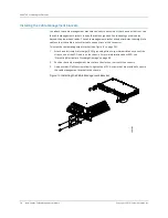


Cabling the Gateway to Management and Alarm Devices
35
CHAPTER 5: Connecting the Gateway
1.
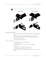
Remove the plug if the SFP transceiver is covered by a rubber safety plug.
2.
Insert the cable connector into the SFP transceiver.
3.
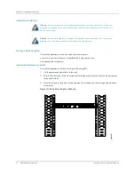
Arrange the cable in the cable management brackets to prevent it from dislodging or
developing stress points. Secure the cable so that it is not supporting its own weight as it
hangs to the floor. Place excess cable out of the way in a neatly coiled loop in the cable
management brackets. Placing fasteners on the loop helps to maintain its shape.
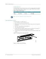
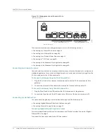
Connecting Ethernet Copper Cables
For cable specifications, see Table 4 and “Ethernet Ports” on page 8.
To connect the gateway to the Ethernet network:
1.
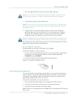
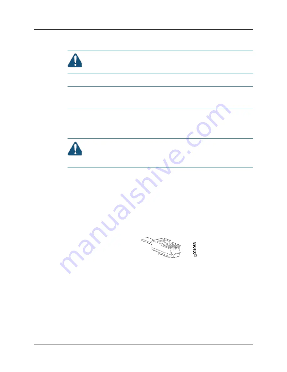
Connect one end of an Ethernet cable with an RJ-45 connector (Figure 20 on page 35 shows
the connector) to one of the available copper Ethernet ports that are labeled from
ETHERNET 0
through
ETHERNET 2
.
2.
Connect the other end of the cable to the appropriate network device.
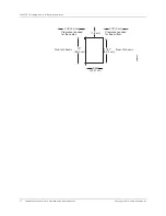
Figure 20: Connector for Ethernet Cable
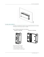
Connecting to an External Alarm Device
To connect the gateway to external alarm-reporting devices, connect wires to the relay contacts
on the front panel. A condition that triggers the red or yellow alarm LED on the front panel also
activates the corresponding alarm relay contact. The alarm relay contacts accept wire of any
gauge between 26-AWG and 24-AWG (0.4 to 0.5 mm
2
).
To connect an external device to the alarm relay contact:
1.
Prepare the required length of single core wire with gauge of 26-AWG or 24-AWG.
2.
Insert wires into the first two consecutive slots of the external alarm contact.
3.
Connect the other end of the wires to the external device.
Repeat the procedure for attaching any other reporting device to the remaining pins of the external
alarm contact.
Caution:
Do not leave a fiber-optic transceiver uncovered except when inserting or removing
cable. The safety cap keeps the port clean and prevents accidental exposure to laser light.
Warning:
Do not look directly into a fiber-optic transceiver or into the ends of fiber-optic cables.
Fiber-optic transceivers and fiber-optic cables connected to a transceiver emit laser light that
can damage your eyes.
Caution:
Avoid bending fiber-optic cable beyond its minimum bend radius. An arc smaller than a
few inches in diameter can damage the cable and cause problems that are difficult to diagnose.
Do not let fiber-optic cable hang free from the connector. Do not allow fastened loops of cable to
dangle, which stresses the cable at the fastening point.
Summary of Contents for BX7000
Page 10: ... x Copyright 2010 Juniper Networks Inc ...
Page 12: ... xii Copyright 2010 Juniper Networks Inc ...
Page 18: ...About This Guide xviii Requesting Support Copyright 2010 Juniper Networks Inc ...
Page 20: ... 2 Copyright 2010 Juniper Networks Inc ...
Page 66: ... 48 Copyright 2010 Juniper Networks Inc ...
Page 90: ... 72 Copyright 2010 Juniper Networks Inc ...
Page 122: ... 104 Hardware Compliance Copyright 2010 Juniper Networks Inc ...
Page 131: ...Copyright 2010 Juniper Networks Inc 113 Appendix E Declaration of Conformity ...
Page 132: ... 114 Copyright 2010 Juniper Networks Inc ...
Page 133: ...Copyright 2011 Juniper Networks Inc 115 PART 4 Index z Index on page 117 ...