JuniAer EMB-312 Assembly & Instruction Manual Download Page 1

T-27 Tucano 20cc 1.2 2022                                                                                                                                               

www.juniaer.com.br


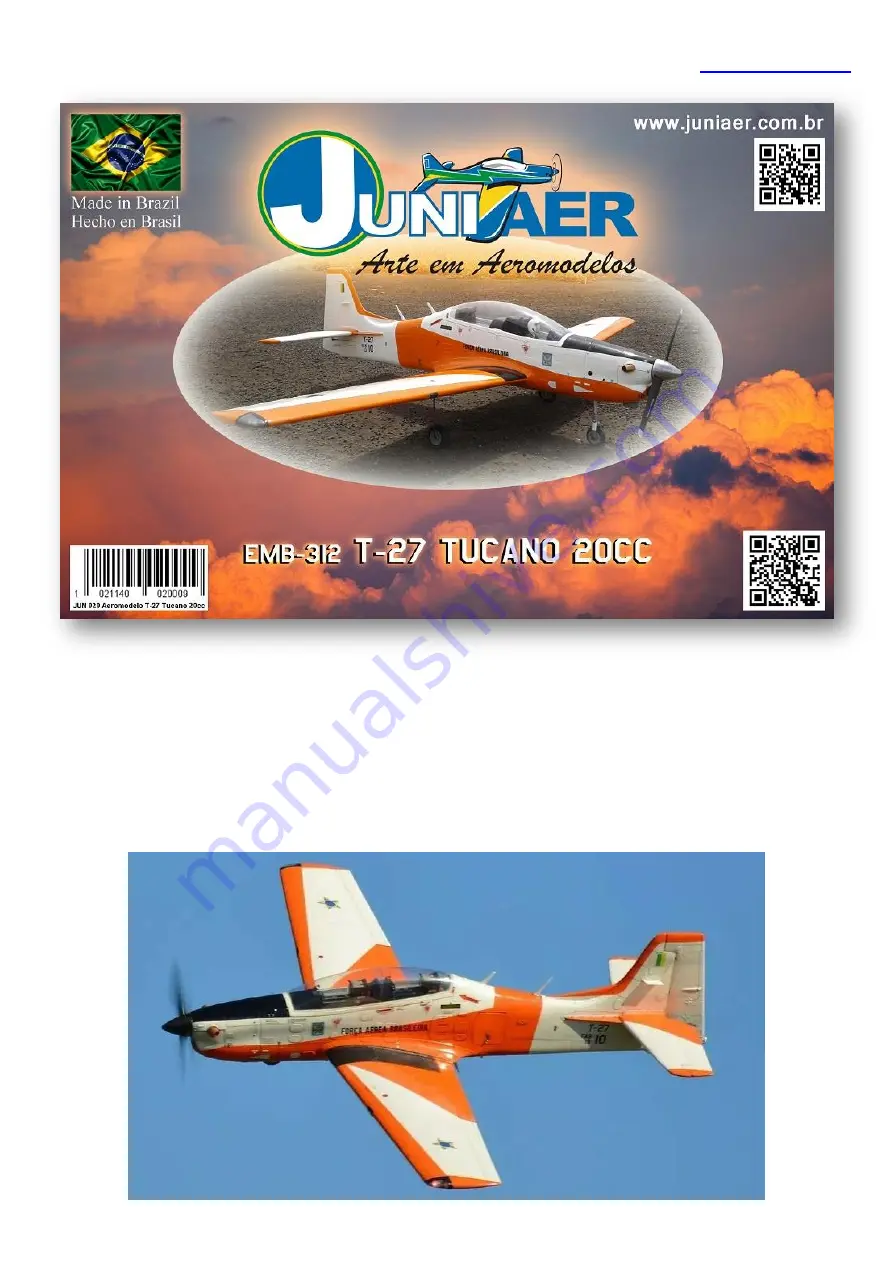
A traditional 20cc sport/scale category model airplane! 

Lots of incredible detail in this classic model airplane with scale, acrobatic and sport flight 

capabilities, bringing precise and smooth performance for the intermediate to advanced level 

model airplane pilot. 


Summary of Contents for EMB-312

Page 1: ...ional 20cc sport scale category model airplane Lots of incredible detail in this classic model airplane with scale acrobatic and sport flight capabilities bringing precise and smooth performance for t...

Page 2: ...on 19 Li Po batteries for electric motors 20 Servos linkage fixing points and commands 21 Ailerons and flaps 23 Elevators 26 Rudder 29 Retracts installation 31 Landing gear doors installation 38 C G C...

Page 3: ...PU varnish or applying epoxy to areas that are uncovered for any reason Avoid exposing the model to direct sunlight as much as possible especially the darker painted parts that accumulate and reflect...

Page 4: ...shows signs of fatigue or wear VERY IMPORTANT Juniaer Modelismo provides a high quality kit with instructions but the quality of the finished model depends on how it is assembled therefore the manufa...

Page 5: ...t ORCN ANATEL or by e mail certificacao anatel gov br We recommend reading the documents cited for legal information about the operation of your model aircraft and the use of Brazilian airspace For re...

Page 6: ...crews holes shall be aligned on the 4 4mm markings on the firewall It is provided a 10mm plywood square part to be used with DLE 20RA to position engine to the front so the prop washer gets in correct...

Page 7: ...e blind nuts through the 10mm square plywood part and the firewall ensuring that a solid firm fixation with parallel alignment between the 4 screws Assemble all engine parts following the manufacturer...

Page 8: ...umstances have contact with parts of the engine block that are very hot during and after operation For this we recommend fixing them to the upright with nylon cable ties firmly and without the possibi...

Page 9: ...screws holes shall be aligned on the 4 4mm markings on the firewall It is provided a 10mm plywood square part to be used with 2 cycle glow engines to position engine to the front so the prop washer g...

Page 10: ...recommend DUBRO Laser Pushrods DUB 500 or DUB 501 as they are flexible and easy to install If you prefer to use steel wire or another metallic pushrod there are no restrictions in the case of glow en...

Page 11: ...location with the correct angles for the engine installation and has markings for 4 engine mount holes The larger hole on the firewall is used for fuel lines and fuel tank ventilation passage and it...

Page 12: ...tion the engine to the engine mount to obtain the throttle and choke pushrods passage location marking the 2 points to allow pushrods passage without obstructions or curves Mark the throttle command l...

Page 13: ...ngine s fuel inlet Pass the silicone hose and pushrod through the holes in the firewall To define the exact position of the engine on the engine mount check the section Installing the engine cowling a...

Page 14: ...ot centered so the engine mount screws holes shall be aligned on the 4 4mm markings on the firewall In the case of an electric motor it is not necessary to use the 10mm plywood part provided with the...

Page 15: ...he mount with nylon cable ties firmly and without the possibility of moving them so that they are routed inside the model aircraft through the hole in the firewall It is recommended that the ESC speed...

Page 16: ...the fuselage apply epoxy glue to 4 10mm hard wood cubes and glue them to the inside of the fuselage in order to make a solid fixing point where the fixing screws will be inserted Do the same for the...

Page 17: ...t air inlet area In gas burning engines we recommend the use of a velocity stack which extends the distance from the carburetor air intake causing the air to be captured inside the fuselage through th...

Page 18: ...tion while 3 blade propellers provide lower RPM being very suitable for scale models however they present a lower speed of response to engine acceleration The JC Super Props are factory balanced paint...

Page 19: ...uel tank via a third way with an independent clunk In this case the tank needs 3 ways of entry and exit clunk 1 that fills empty the tank clunk 2 that sends fuel to the engine and vent line for the ex...

Page 20: ...internal fuel tank connections left safety clips for connections center and fuel filter with safety clips on connections right Above fuel tank assembly scheme with 1 clunk vent line and third line fo...

Page 21: ...mand surfaces and throttle 2 for ailerons 2 for flaps 1 for rudder and 1 for throttle Suggestions FUTABA S 3004 HOBBICO CS 64 HOBBICO CS 126 SAVOX B06KG SAVOX SAVSC0253MG And 2 mini servos with 4kg cm...

Page 22: ...ACCIDENTS AND TOTAL OR PARTIAL LOSS OF THE MODEL AIRPLANE OFFERING RISKS TO PEOPLE AND PROPERTIES AROUND THE FLYING AREA THE WING TRAILING EDGES AT THE AILERONS AND FLAPS AND THE STABILIZER TRAILING E...

Page 23: ...drop of medium CA glue or epoxy glue to each hole It is necessary to open a slot in the servo compartment cover to pass the servo arms as shown in the photos To fix the servo compartment cover apply a...

Page 24: ...rt screwdriver to keep the screw angle at 90 in relation to the ribs as there is little internal space It is necessary to open a slot on the servo compartments covers to pass the servo arms as shown i...

Page 25: ...servos compartment covers showing servo fixation points at the ribs Above aileron and flap servos installed on the ribs for attachment left and position of the horns servo arms and aileron and flap co...

Page 26: ...ncidence 0 degrees The drawing below shows the position of the 3 holes and pin Insert the wing halves Check that the wing roots are perfectly aligned with the shape of the wing on the fuselage Insert...

Page 27: ...rs of the servos boxes to pass the mini servos arms as shown in the photos To fix the servo box covers apply a drop of medium CA glue or epoxy 5 minutes in each hole for better fixation and vibration...

Page 28: ...the top and bottom Before gluing apply adhesive tape masking tape on the parts close to the gluing area both on the fuselage and on the stabilizer to later remove the excess that will come out when s...

Page 29: ...epoxy glue with a toothpick filling all contact areas and insert the 3 hinges until the hinge center is aligned with the rudder deflection line Check that the hinges are all correctly aligned includin...

Page 30: ...n 10mm low rate to 15mm high rate up and down Rudder Between 30mm low rate to 45mm high rate left and right Flaps Between 0 to 10 for take off we recommend 0 and between 25 to 30 for landing Standard...

Page 31: ...he retracts bases and compartments The wing retracts fixing bases are made in 10mm plywood and the front ones in epoxy resin with 10mm plywood and are solid enough to withstand the efforts required by...

Page 32: ...et Direct connection to receiver internal controller Made from drawn and ground 316 stainless steel Aluminum magnesium alloy die cast forks Rectified steel shock absorbers Supplied with 90 machines un...

Page 33: ...steel Aluminum magnesium alloy die cast forks Rectified steel shock absorbers Supplied with 90 machines with paint and wheels Wheel axles 5mm Total weight 720g JP ER 120 V 2 controller with gear door...

Page 34: ...proper voltage for both the controller and the servos used It is necessary to connect the electronic controller to a designated receiver channel to control the landing gear position extended or retrac...

Page 35: ...c Juniaer mounting dimensions Electromagnetic brakes on the 2 main wheels Includes 2 front wheel control arms and metal pull pull controls 1 replacement bushing for the front landing gear and 1 allen...

Page 36: ...er normal operating conditions VERY IMPORTANT Landing gear door servos should be high voltage 7 4V Check the proper voltage for both the controller and the servos used It is necessary to connect the e...

Page 37: ...NECTION TO THE CONTROLLER OR THE ELECTRIC MOTORS MAY BURN OUT VOIDING THE PRODUCT WARRANTY Retract set operation sequence with the V 2 controller option 1 Turn on radio and receiver setting EPA or ATV...

Page 38: ...The landing gear doors are supplied in unique pieces that need to be cut and reinforced for installation The landing gear doors are exposed to situations of high vibration and air displacement so they...

Page 39: ...attach them to the external doors glue them with 30 to 40 minutes epoxy glue as shown in the pictures below A simpler installation option is to attach the outer doors directly to the main landing gear...

Page 40: ...c pistons It is necessary to install a short horn on the front or center of the doors for the linkage Above The 2 front doors of the front landing gear in open position with the front retract extended...

Page 41: ...t necessary to add weight to obtain the correct balance of the C G and the position of the Li Po batteries must be defined at the end of the assembly In the case of gas burning engines balancing is mo...

Page 42: ...t Components 11 000K white light 3w light emitting power with 120 lens 1 led is used on each side of the wing Leds wing landing lights Type SMD white light 11 000K light output power 2W each 2 leds ar...

Page 43: ...the wing and pull the plate to the outside Repeat the same process for the other half of the wing Above weight on thread tip to pass the wires and wire to pull the wing landing light plates left To fi...

Page 44: ...t from set Above desired parts shape Above clear plastic parts glued at correct places To pass the rudder wires inside the fuselage position it with the rudder facing upwards and do the same process u...

Page 45: ...ge when gas burning engine is used for correct C G balance Below are some examples of assemblies and installations of this equipment Always remember to fix all components very well and lock all splice...

Page 46: ...h a hinge and lock supplied with the kit Inside there is enough space to easily install on off switches air supply pressure gauges tachometer access to charge batteries voltage monitors etc Above inte...

Page 47: ...Juniaer made of fiberglass with epoxy resin low weight painted and varnished according to the painting scheme for greater realism Base width 7cm base length 3 7cm height 6 5cm and weight 17g To glue t...

Page 48: ...separately custom cockpits for your T 27 Tucano 20cc Juniaer extremely detailed and realistic ready for installation to replace the stock cockpit Available in shallow cockpit for pilot s busts Cockpi...

Page 49: ...he contact points of the canopy frame where the canopy will be glued for better adhesion To glue use white canopy glue and attach the canopy set canopy frame to the fuselage with good adhesion masking...

Page 50: ...d Above Sand the contact area of the frame to increase glue adhesion left and apply white glue to the entire contact area right Above canopy and frame position in the fuselage fixed in place with adhe...

Page 51: ...without friction or deformation see photos below Make a simulation of opening and closing before fixing the hinges permanently If necessary depending on the hinges used make slots on the fuselage edge...

Page 52: ...the lever to pass outside the fuselage and fix the lock on the inside with 30 to 40 minutes epoxy glue considering the position of the horn or servo arm so that the closing is very tight and secure Ab...

Page 53: ...am com juniaermodelismo 35 3591 1036 fixo twitter com Juniaer You Tube JUNIAER T 27 Tucano 20cc transport and protection covers We provide sold separately protective and transport covers made of durab...

Reviews: