background image

1002

.GB

B 4

3

Technical data - standard version

A

Indication of technical data according to VDI 2198.
Subject to modification and supplementing.

3.1

Performance data

*

Even distribution across the entire fork length. 

Designation

EKE 30-2ac

Q Rated load capacity

3000

kg

c

Load centre distance at
standard fork length *

)

1800

mm

Travel speed 
with/without rated load

18.1 / 18.3

km/h

Lifting speed
with/without rated load

2.6 / 3.0

cm/s

Lowering speed
with/without rated load

3.0 / 2.9

cm/s

h

3

h

13

m

2

l

2

l

1

l

y

1000 kg

1000 kg

1000 kg

290

h

7

b

10

b

2

b

5

e

1745

1980

s

a

_
2

a

_
2

A

st

W

a

b11

Summary of Contents for EKE 30-2 ac

Page 1: ...Operating instructions 50272276 EKE 30 2 ac G 08 02 09 03...

Page 2: ...explanations are indicated by the following graphics f Used before safety instructions which must be observed to avoid danger to personnel m Used before notices which must be observed to avoid materi...

Page 3: ...0108 GB...

Page 4: ...5 Technical description load lifting devicet B 7 4 Label positions and identification plates B 7 4 1 Truck identification plate B 8 C Transportation and commissioning 1 Transportation by crane C 1 2 C...

Page 5: ...tal protection F 1 2 Safety regulations applicable to truck maintenance F 1 3 Servicing and inspection F 3 4 EKE 30 2 ac maintenance checklist F 4 5 EKE 30 2 ac lubrication schedule F 6 5 1 Fuels cool...

Page 6: ...lf or on whose behalf it is used In special cases e g leasing or renting the user is conside red the person who in accordance with existing contractual agreements between the owner and the user of the...

Page 7: ...0600 GB A 2...

Page 8: ...with an open bottom or with cross pieces or trolleys outside the load wheel area The capacity is indicated on the identification plate and also on the capacity plate Qmax The fork dimensions match the...

Page 9: ...LISA 8 t Accelerator pedal 2 t Hydraulics control knob 9 t Driver seat 3 t Parking brake 10 t Lifting device 4 t Key switch 11 t Drive wheels 5 t Main switch EMERGENCY STOP 12 t Emergency steering sw...

Page 10: ...ivoted gears can be swiveled by 90 to both sides Controls and indicators Controls and indicators are clearly arranged at the driver position The hydraulics control knob 2 allows single handed operatio...

Page 11: ...e entire fork length Designation EKE 30 2ac Q Rated load capacity 3000 kg c Load centre distance at standard fork length 1800 mm Travel speed with without rated load 18 1 18 3 km h Lifting speed with...

Page 12: ...ork 90 5 l1 Overall length 4855 l2 Front section length 1255 b2 Truck width 1000 b5 Distance between forks outside 580 b10 Track width drive 604 b11 Track width load section 380 Wa Turning radius 3900...

Page 13: ...ned by driving over bumps with a constant speed Electromagnetic compatibility EMC The manufacturer confirms compliance with the limit val ues for electromagnetic emission and interference immu nity as...

Page 14: ...Label positions and identification plates Item Designation 14 Truck identification plate 15 Carrying capacity Qmax 16 Eye for crane loading 17 Label Danger of squeezing 18 UVV test plaque 17 16 16 15...

Page 15: ...in kg 22 Battery Voltage in V 29 Dead weight without battery in kg 23 Manufacturer 30 Year of manufacture 24 Order No 31 Manufacturer s logo 25 Load centre distance in mm kg kg mm kg Xxx Xxxx Xxxxxxx...

Page 16: ...r to chapter E Secure the truck against inadvertent rolling away with wedges m Attach the crane hoisting equipment at the lifting points in such a way that it cannot slip for any reason and that it do...

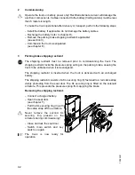
Page 17: ...ng the truck The shipping restraint locks the pressure spring acting on the parking brake causing the truck to be unbraked when it is deenergised The shipping restraint is inserted when the truck is d...

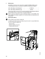
Page 18: ...cable shoes must be clean lightly greased with pole grease and must be securely tightened Batteries with bare terminal posts must be covered using a non skid insulating mat Disposal of the battery Ba...

Page 19: ...lating mat f Battery weight and dimensions have considerable influence on the stability of the truck Changing the battery equipment is not permitted without prior approval by the manufacturer 3 Exposi...

Page 20: ...n the battery Prior to starting the recharging operation check all cable connections and plugged connections for visible damage Connect the charging cable 4 of the battery charger with the battery con...

Page 21: ...lifting gear must pull in a vertical direction to prevent damage to the battery trough The hooks must be fastened in such a way that they cannot fall onto the battery cells when the crane hoisting gea...

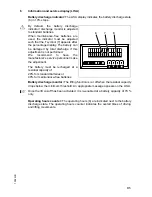
Page 22: ...e recommend to have the manufacturer s service personnel make the adjustment The battery must be recharged at a residual capacity of 20 for standard batteries or 40 for maintenance free batteries Batt...

Page 23: ...1002 GB D 6...

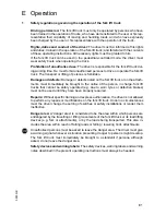
Page 24: ...uck or on the attach ments must immediately be brought to the notice of the person in charge fork lift trucks that cannot be safely operated e g due to worn tyres or defective brakes must not be used...

Page 25: ...ch t Switches the truck s battery voltage on and off Red key No 702 for the operator Grey key No 738 for service and workshop personnel 11 Main switch EMERGENCY STOP t The circuit is interrupted all e...

Page 26: ...E 3 0903 GB 1 2 17 18 12 13 14 19 15 16 3 4 5 6 7 8 9 10 11 20...

Page 27: ...tion Sit on the driver seat Pull driver seat locking lever 17 upward and set driver seat to the desired seating position by sliding it forward or backward Let the locking lever engage again Turn the h...

Page 28: ...1 must not be pinched or chafe on sharp edges Switching on the truck A When the truck is parked the running surface of the tyres will flatten These flattenings will disappear after travelling for a wh...

Page 29: ...ched on Emergency stop The truck is automatically braked down until it stops if a steering system malfunction occurs during driving that might impair the driver s safety Emergency stop reset Switch th...

Page 30: ...always be carried at that end of the truck facing uphill U turns cutting obliquely over slopes or inclines and parking of the fork lift truck on slopes or inclines is not permitted Inclines must only...

Page 31: ...avelling Drive when hoods are properly closed and locked only Start up the truck see section 3 Disengage the parking brake 9 switch by pressing it Set the travel direction switch 8 to the desired dire...

Page 32: ...the brake pedal 15 Braking by means of counter current brake Set travel direction switch 8 to the opposite travel direction while the truck is stil moving The travel current controller brakes the tru...

Page 33: ...t is reached Lowering Press the hydraulic control knob Lower load lifting device 6 until the desired height is reached A The lowering speed is set to a fixed value and cannot be regulated 4 4 Safe par...

Page 34: ...ssible cause Remedial action Truck does not move Battery connector not connected Check battery plug and plug in if necessary Main switch EMERGENCY STOP pressed Unlock main switch EMERGENCY STOP Key sw...

Page 35: ...e cable 22 from the deflection pulley 23 This releases the parking brake f Steering at standstill tenses the tyre of the drive wheel This may cause the wheel to turn back when the crank is released Se...

Page 36: ...ed Set both steering wheels straight by turning the star grips 24 The straight position can be verified by inserting a 6 mm pin in the index bores 26 Close and lock the driver door and the steering co...

Page 37: ...0903 GB E 14...

Page 38: ...ians trained especially for these assignments We thus recommend signing a maintenance contract with the relevant service location of the manufacturer Lifting and jacking up When a fork lift truck is t...

Page 39: ...he quality of the tyres greatly affects the stability and the driving behaviour of the fork lift truck The factory mounted tyres must only be replaced by original spare parts of the manufacturer since...

Page 40: ...are defined as follows W1 every 50 operating hours but at least once per week M3 every 500 operating hours but at least every 3 months M6 every 1000 operating hours but at least every 6 months M12 eve...

Page 41: ...ssion oil level t 2 3 Change transmission oil l t Wheels 3 1 Check for wear and damage t 3 2 Check bearing and secure attachment a l t Steering 4 1 Check the steering play t 4 2 Check the steering cha...

Page 42: ...erminals for secure attachment and apply grease l t 9 3 Clean battery plug connections check for tight seat l t 9 4 Check battery cables for damage and replace if necessary t 9 5 Ckec the battery lock...

Page 43: ...surfaces s Lubricating nipples Hydraulic oil filler neck b Gear oil filler neck a Gear oil drain plug Cold store application t Brake fluid filler neck 1 Blending ratio for cold store application 1 1 s...

Page 44: ...escribed in these operating instructions Avoid spilling Spilt liquid must be removed immediately using a suitable binding agent and the mixture of consumption type material and binding agent is to be...

Page 45: ...see chapter D f When work has to be performed under the lifted load lifting device or truck suitable measures must be taken to prevent any dropping tilting or slipping of the truck When lifting the i...

Page 46: ...efully swing down the steering controller 5 Loosen and remove the screws 6 of the ventilation plate 7 Remove the ventilation plate Loosen and remove the screws 8 of the cover plate 9 Remove the cover...

Page 47: ...he table and replace them if necessary Item Designation Protects Rating 10 2F1 Pump motor 160 A 11 F8 Main fuse 355 A 12 3F6 Steering motor 30 A 13 F1 Key switch 30 A 14 1F9 Control voltage for travel...

Page 48: ...more than 6 months additional meas ures must be discussed with the Service Department of the manufacturer 7 1 Operations to be performed prior to decommissioning Thoroughly clean the fork lift truck...

Page 49: ...k ked by a qualified inspector The inspector must assess the condition of the truck from a standpoint purely concerned with safety aspects uninfluenced by any company or economic circumstances The ins...

Reviews: