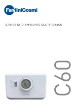
Room thermostat (1-way NC contact) 230 V
Figure 3: Clampable conductor cross-section
■
Connect electrothermal valve drive (7) to insert (1) according to connection diagram
(Figure 2). Observe the conductor cross-sections (Figure 3).
■
Fit device in appliance box; terminals must be at the bottom.
■
Fit the frame, central plate and control knob.
■
Switch on mains voltage.
The unit calibrates itself within the first 90 minutes. Control deviations are possible during
this period.
Setting the temperature limits
The room temperature controller has a setting range of 5 ... 30 °C. The adjustment rings on the
central plate can be used to limit the temperature setting range.
Figure 4: Setting the temperature limit (before/after)
■
Pull the control knob off the central plate so that the adjustment rings are visible Bild.
Pulling off is done by hand or with a suitable tool, e.g. vacuum lifting tool or key cap puller.
■
Turn the large blue adjustment ring clockwise to the desired minimum temperature. Each
notch corresponds to a change of about 1 °C.
■
Turn the small red adjustment ring anticlockwise to the desired maximum temperature.
The respective adjustment ring can only be turned in one direction. To return to the ori-
ginal setting, continue turning to the respective position.
■
Replace the control knob, observing the coding (Fig. 4, bottom) of the control knob and
rotary axle.
3 / 4
82404803
05.05.2022
J0082404803


