Jung NRS 0834 AT Series Manual Download Page 2

2                                                                

Short description 


In accordance with DIN VDE 0834, the emergency system set is meant to be used in 

bathrooms for people with disabilities. The DIN VDE 0834 must be considered during 

installation and operation of the emergency system. 


The set is comprised of: 

  Emergency signal   


NRS .. 0834 RM .. 

  Pull cord push-button 


NRS .. 0834 ZT .. 

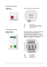
  Reset button  


NRS .. 0834 AT .. 

  Power supply 


NRS .. 0834 NT .. 


Only included in the emergency system set with UPS (NRS .. 0834-2 ..): 

  UPS module  


NRS .. 0834 USV .. 


Available separately: 

  Service unit   


NRS .. 0834 DZE .. 

  Call button   


NRS .. 0834 RT .. 

  Service terminal 


NRS DZT 20 WW 

  Surface-mounted housing for service terminal   

NRS DZT AP WW 

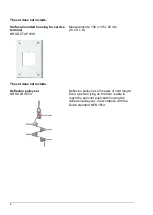
  Deflexion pulley set  


NRS ULR 0834 


Spare parts: 

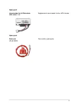
  Accumulator for UPS module 


NRS AKKU 130 

  Pull cord 


ZS-34 KO5S 


Functional description 

When an emergency call is triggered with the pull cord, the red light on the push-button 

confirms the successful call. The emergency call is indicated visually and acoustically by 

the emergency signal. In stand-by mode, a light makes it easier to find the pull cord push-

button. 


For other use cases, the visual and acoustic call can be transformed into a continuous 

signal, for example, using a jumper. It is also possible to disable the acoustic call. 

The unmonitored call can be sent from the emergency signal via a floating contact. 


Pressing the reset button stops the emergency call. 


If there is no superordinate emergency power supply, the UPS module must be used. The 

UPS module ensures that the emergency call is triggered even in the event of power 

failure. The accumulator included is easy to replace and available as a spare part. This 

emergency power supply is monitored, every disruption is reported. 

In battery mode, a short acoustic signal is sent to the emergency signal every 12 seconds. 

Two short acoustic signals every 12 seconds are sent to the emergency signal to indicate 

an accumulator disturbance. 


Summary of Contents for NRS 0834 AT Series

Page 1: ...1 Manual Emergency system set NRS 0834 Emergency system set with UPS NRS 0834 2...

Page 2: ...push button confirms the successful call The emergency call is indicated visually and acoustically by the emergency signal In stand by mode a light makes it easier to find the pull cord push button Fo...

Page 3: ...vice terminal in absence or interrupted for 20 seconds Surface mounted housing is optionally available In accordance with the Dutch standard NEN 1814 the length of the pull cord of the push button can...

Page 4: ...tton KA Make contact KR Break contact KW Contact input M Service unit terminal GND Power supply 24V Power supply The external connections are intended for downstreamed components pull cord push button...

Page 5: ...5 Reset button NRS 0834 AT Reset button for call silencing AT Reset button IN AT Reset button OUT Power supply NRS 0834 NT With blank cover for flush mounted installation...

Page 6: ...several hours Operation and disturbance of the accumulator are monitored and reported 24V OUT 24V external OUT GND GND external OUT M Emergency signal terminal GND Power supply IN 24V IN Power supply...

Page 7: ...WC call The set does not include Service terminal NRS DZT 20 WW Optional module for unmonitored forwarding of up to 20 calls Separate terminals for 20 circuits for closed and open circuit mode An addi...

Page 8: ...ments 100 x 145 x 25 mm W x H x D The set does not include Deflexion pulley set NRS ULR 0834 Deflexion pulley set 20 meters of cord length Even a person lying on the floor is able to reach the pull co...

Page 9: ...9 Spare part Accumulator for UPS module NRS AKKU 130 Replacement accumulator for the UPS module Spare part Pull cord ZS 34 KO5S Pull cord for pull inserts...

Page 10: ...s Mounting installation and commissioning is only permitted for electricians When working on systems supplied with AC 230 V the safety requirements in accordance with DIN VDE 0100 must be observed Whe...

Page 11: ...batteries Replace batteries only with an identical or equivalent type Remove empty batteries immediately and dispose of in an environmentally friendly manner Settings Settings on the emergency signal...

Page 12: ...e floor Signal lights and text displays 1 5 to 2 2 m above the floor DIN 18024 2 Accessibility also prescribes to install operational elements for wheelchair users at a height of 0 85 m Installation a...

Page 13: ...13 Installation Wiring of standard system...

Page 14: ...in flush mounted box 58 mm cover Emergency signal installation in flush mounted box 58 mm cover floating relay contact 2 way 24 V 2 A Pull cord push button reset button service unit call button UPS m...

Page 15: ...ergency signal RT AT 24 V and GND are connected in parallel Typical use case for bathrooms which are accessible from the corridor but with some distance to the main entrance One emergency signal repor...

Page 16: ...ith additional call button The additional call button is monitored Here the built in status light gives feedback For the function of the status light to be in accordance with the norms there must not...

Page 17: ...h additional pull cord push button An additional pull cord push buttons are available for the emergency system set For the function of the status light to be in accordance with the norms there must no...

Page 18: ...g plan Emergency system set with additional reset button Reset button are connected in parallel Example wiring plan Emergency system set with additional service unit Up to 2 service units can be conne...

Page 19: ...riggered by additional push buttons Triggering the call additional using another push button e g in the toilet support bracket is possible For this RT must be connected via an NC contact The call is t...

Page 20: ...20 Example wiring plan Unmonitored call The emergency signals have a floating relay contact DC 24 V 1 A which is suited for unmonitored calls...

Page 21: ...light signal if GNDE and RT are connected As long as power is supplied a call will be issued Not suitable for monitored calls It is recommended in certain cases even required to use an additional powe...

Page 22: ...set should include a second emergency signal and a service unit Emergency signal 1 x 65 mA Emergency signal 1 x 65 mA Pull cord push button 1 x 19 mA Service unit 1 x 57 mA 206 mA Operation is permiss...

Page 23: ...ters must be used Example 1 A service unit at a distance of 150 m is to be connected with a J Y St Y 4x2x0 6 wire According to table 1 this results in a loop resistance of 18 37 ohm and is lower than...

Page 24: ...into household waste Consult your local authorities about environmentally friendly disposal According to statutory provisions the end consumer is obligated to return used batteries Warranty We offer...

Reviews: