o
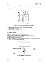
Activate programming mode: Press and hold pushbutton (17). Then press pushbutton
(18).
The operation LED (19) flashes quickly.
o
Load the physical address into the device.
The operation LED (19) returns to its previous state – off, on, or flashing slowly.
o
Write the physical address on the device label.
o
Load application software into the device.
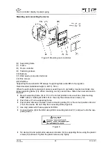
Mounting the control surfaces
The control surfaces are available as a complete set of buttons. Individual buttons can be
replaced using buttons with icons.
i
The mounting spider is not required to mount the buttons.
The physical address is loaded into the device.
o
Place control surfaces on the device in the right orientation and snap in with a short push.
6 Appendix
Disposal
Please consider your local regulation for disposal and electronic waste recycling.
6.1 Technical data
KNX medium
TP
Commissioning mode
S-mode
Rated voltage KNX
DC 21 ... 30 V SELV
Current consumption KNX
max. 20 mA
Connection mode KNX
device connection terminal
Ambient temperature
23 ... 113 °F
(-5 ... +45 °C)
Storage/transport temperature
-13 ... +158 °F
(-25 ... +70 °C)
Protection class
III
Purpose of control
Operating Control
Construction of control
Independently Mounted Control for Flush
Mounting
Pollution Degree
PD 2
Impulse Voltage
330 V
6.2 Accessories
Cover kit 1-gang
Order No. ..401TSA..
Cover kit 2-gang
Order No. ..402TSA..
Cover kit 3-gang
Order No. ..403TSA..
Cover kit 4-gang
Order No. ..404TSA..
Push-button extension module, 1-gang
Order No. 4091TSEM01
Push-button extension module, 2-gang
Order No. 4092TSEM01
Push-button extension module, 3-gang
Order No. 4093TSEM01
Push-button extension module, 4-gang
Order No. 4094TSEM01
6.3 Warranty
If you have any questions about this product, contact:
Jung USA, Inc.
350 Fifth Avenue, Suite 5220
New York, NY 10118
Phone: +1 800.311.6135
Email: [email protected]
www.jungcontrols.com
For the product warranty, please refer to the attached document.
All rights reserved
7/8
Room controller display module 2-gang
82574805
J0082574805
29.06.2017

