background image

KNX push-button universal / KNX push-button standard / KNX push-button
extension

6.2 Commissioning

Preconditions in secure operation

A dedicated application program is required.

Secure commissioning is activated in the ETS.

Device certificate entered/scanned or added to the ETS project. A high resolution camera
should be used to scan the QR code.

Document all passwords and keep them safe.

Programming the physical address and application program

Project design and commissioning with ETS from  version5.7.3and above.

Figure 6: Buttons for activating Programming mode

Activation of the programming mode without attached rockers.

Precondition: The device is connected and ready for operation.

Activate programming mode: Press and hold push-button at the upper left (9). Then press
push-button at the lower right (10) (Figure 6).
The status LEDs flash rapidly (approx. 8 Hz). Programming mode is activated.

Load the physical address into the device.
The status LEDs return to their previous state – off, on, or flashing. Physical address is
programmed.

Write the physical address on the device label.

Load the application program into the device.

The status LEDs flash slowly while the application program is programmed (approx. 0.75
Hz). As soon as the programming is successfully completed, the status LEDs carry out
their parameterised function.

If the device contains no – or an incorrect – application program, both status LEDs flash
slowly (approx. 0.75 Hz).

Safe-state mode

The safe state mode stops the execution of the loaded application program.

Only the system software of the device is still functional. ETS diagnosis functions and pro-
gramming of the device are possible.

Activating the safe-state mode

Switch off the bus voltage.

Press and hold down the top left button and bottom right button (Figure 6).

Switch on the bus voltage.
The safe-state mode is activated. The status LEDs flash slowly (approx. 1 Hz).

Only release the the top left and bottom right buttons when the LEDs flash.

8 / 12

82402103

19.02.2020

J0082402103

Summary of Contents for 10711ST Series

Page 1: ...t no 10721ST KNX push button extension 1 gang Art no 10911TE KNX push button extension 2 gang Art no 10921TE Operating instructions 1 Safety instructions Electrical devices may only be mounted and con...

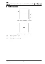
Page 2: ...on standard KNX push button extension 2 Device components Figure 1 Device components 1 channel Figure 2 Device components 2 channel 1 Design frame accessories 2 Status LED 3 Operating rockers accessor...

Page 3: ...nning installation and commissioning of the device are carried out with the aid of the ETS version 5 7 3 and above Intended use Operation of loads e g light on off dimming Venetian blinds up down brig...

Page 4: ...tion Button function Two buttons above one another per form the same function Each button can perform an indi vidual function Universal For the rocker functions Dimming Venetian blind and 2 channel op...

Page 5: ...unting with 230 V socket outlets under a common cover there is a danger of electrical shocks in the event of a fault Use only the enclosed plastic screws for fastening to the supporting frame Mount su...

Page 6: ...ol our coding black SW red RT white WS yellow GE The connection terminal blocks are included with the Do not exceed the cable length max 30 m One Push button universal can be connected per Do not conn...

Page 7: ...KNX push button universal KNX push button standard KNX push button extension Do not connect any external voltage Figure 5 Connecting installation push button 7 12 82402103 19 02 2020 J0082402103...

Page 8: ...physical address into the device The status LEDs return to their previous state off on or flashing Physical address is programmed Write the physical address on the device label Load the application p...

Page 9: ...a master reset The status LEDs flash rapidly approx 4 Hz The device restarts The status LEDs flash slowly approx 0 75 Hz Only release the the top left and bottom right buttons when the LEDs flash Res...

Page 10: ...ng the operating rockers Figure 7 The operating rockers can be dismantled using a dismantling wedge or a screwdriver Figure 8 The recesses are intended for a blade width of up to 4 mm Figure 7 Dismant...

Page 11: ...tion terminal Connecting cable KNX EIB Y St Y 2x2x0 8 Protection class III Push button extension connection see accessories Number 1 Cable type J Y St Y 2 2 0 8 Cable length max 30 m External switchin...

Page 12: ...rranty The warranty is provided in accordance with statutory requirements via the specialist trade ALBRECHT JUNG GMBH CO KG Volmestra e 1 58579 Schalksm hle GERMANY Telefon 49 2355 806 0 Telefax 49 23...

Reviews: