


16
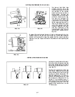
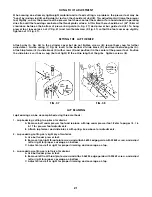
SETTING THE PRESSER FOOT (CONT.)
Turn the handwheel in operating direction until link (A,
Fig. 20) has traveled fully to the front. There must be a
1/64" (0.4mm) clearance between link (A) and the back
of needle head (B) when link (A) starts to jackknife.
Loosen screw (C) and rotate driving sleeve (D) to posi-
tion link (A). Tighten screw (C).
Add the cover thread hook(F) and cover thread carrier(E)
if they are not in place. Position carrier so the thread
loop will be carried behind the first two needles. There
should be a minimum 1/64"(0.4mm) clearance between
the hook and the carrier at their closest position.
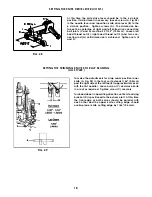
Replace the presser spring and the presser bar regulating screw.
Loosen screws (A, Fig. 22) in lifter lever link assembly (B) and position
lever (C) so there is 1/32" (0.8mm) clearance between it and presser
bar guide (D) when the feed dogs are below the throat plate.
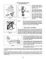
When the hook swings to the left it will pass over the cover thread. On
its return travel, the thread will "pop" into the slot on the underside of
the hook and is carried to the right. This thread forms a triangle for
the third and forth needle threads to pass through. As the cover
thread "pops" into the slot it must cast-off the high point of take-up (A,
Fig. 23) at the same time. Loosen the two screws in the cover thread
take-up and reposition if necessary. If there is difficulty in making
this adjustment, check the thread tension and make sure the hook
point has an extremely high polish and the angle is correct. Due to
clearance requirements bending the hook is not recommended.
FIG. 21
FIG. 22
FIG. 23
Summary of Contents for UnionSpecial 36200UAD52
Page 7: ...7 THREADING 36200 0 0 MACHINE...
Page 22: ...22 9 16...
Page 24: ...24 2 31 18 17 14 ____ 12 19 4 3...
Page 26: ...26 3...
Page 28: ...28 21 T19DRQUE TO 21 22 241n lbs cm kg I...
Page 30: ...30 15 12 6 j 38 I I 44 37 28...
Page 40: ...40 4 40 i li l rrrt l 1 i r C J 4 12 2 27 32 172 2mml 3 5 32 180 2mmJ...
Page 44: ...44 16 27 Torque to 18 rt lbso I...
Page 46: ...46 11 3...
Page 48: ...48 1 17A...
Page 50: ...50...
Page 52: ...52 2 4 4 5 8 9 10 20 15 21 25...
Page 56: ...56 1 4...
Page 58: ...58 17 18 8 7 6...


