background image

– 4 –

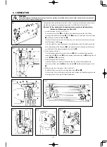
 6. LUBRICATION

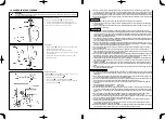
Lubricate the arrow points shown in Fig. 1 and 4. They must be lubricated at least twice a 
day when the machine is continuously operated. Use JUKI New Defrix Oil No. 1.

(Caution)  Before starting the fi rst operation of your newly installed machine, 

lubricate the following parts without fail.

1.  Needle bar crank (See Fig. 2 a~d Fig. 5) 
 

Pour oil into the oil hole 

1

 on the front of the machine arm, and the oil will 

fl

 ow 

through main shaft front bushing 

2

, oil felt 

3

 and the oil wick and will reach oil pipe 

4

 to lubricate needle bar crank rod 

5

.


On the other hand, another oil wick allows the oil to lubricate the needle bar through 
needle bar upper bushing 

6


Thus, the needle bar crank mechanism is completely lubricated. After lubrication, the 
used oil gathering in the front part 

7

 of the machine arm is collected by the drip pan 

on the bottom of the machine through oil return felt 

8

.

2.  Feed mechanism (Fig. 3) 
 

The lubricating oil poured into the oil reservoir 

9


fl

 ows to lubricate feed regulator 

connecting link 

!3

,

 pit-man 

!4

 and feed driving shaft connecting rod 

!5

 through the oil 

wicks 

!0

!1

 and 

!2

 respectively.

3.  Feed driving and feed bar (Fig. 4) 
 

Lubricate all the arrow points as illustrated from the bottom of the machine bed. 


The center of feed rock shaft 

!7

 and feed bar shaft 

!8

 are lubricated through oil wick 

!6

.

4. Filling the gear case with grease. (Fig. 6 and Fig. 7) 
 Regularly 

fi

 ll the gear case by removing plug screws 

!9

 and 

@00


As soon as the oil seals which prevent grease from leaking are found damaged or worn 
after long period of use, replace them immediately.

Fig. 1

Fig. 2

Fig. 3

Fig. 4

Fig. 5

Fig. 6

Fig. 7

WARNING :

To avoid possible personal injury due to abrupt start of the machine, turn off the power to the machine and check to be sure that the 
motor has totally stopped rotating in prior.

1

3

4

6

5

2

8

7

6

5

8

7

!0

9

!1

!2

!3

!4

!5

!6

!7

!8

!9

@0

vii

DECLARATION OF INCORPORATION OF PARTLY COMPLETED MACHINERY

We hereby declare that the sewing machine (sewing head) described below ;

1. Must not be put into service until the machinery to which it is incorporated has been declared in

conformity with the provisions of the Directive 2006/42/EC, and

2. Conforms to the essential requirements of the Directive 2006/42/EC, described in the technical 

documentation, and

3. To be prepared with the above technical documentation compiled in accordance with part B of 

Annex VII, and

4. Also to conform to the RoHS Directive 2011/65/EU
5. Relevant information on which should be transmitted in response to a reasoned request by the 

national authorities, by the electronic method or other according to the request.

Applied harmonized standards, in particular :
EN ISO12100, EN ISO10821, EN 50581

Manufacturer :

JUKI CORPORATION
2-11-1, Tsurumaki, Tama-shi, Tokyo, Japan

Model
Description

Industrial Sewing Machine

Function

make stitches and sew

ML-111

Summary of Contents for ML-111

Page 1: ...NOTE Read safety instructions carefully and understand them before using Retain this Instruction Manual for future reference INSTRUCTION MANUAL ML 111 No 02 40095701...

Page 2: ...eFWiRn PiFWRrial Zarning inGiFaWiRn e aZare WKaW KRlGing WKe VeZing PaFKine GXring RSeraWiRn Fan KXrW RXr KanGV TKere iV a riVN RI eleFWriFal VKRFN iI FRnWaFWing a KigK YRlWage VeFWiRn TKere iV a riVN...

Page 3: ...Rne NeYer PRGiI anG alWer WKe PaFKine in RrGer WR SreYenW aFFiGenW WKaW Fan reVXlW in SerVRnal inMXr Rr GeaWK U I aVVXPeV nR reVSRnVibiliW IRr GaPageV Rr SerVRnal inMXr Rr GeaWK reVXlWing IrRP WKe Pa...

Page 4: ...VeleFW Rne ZiWK an enWan glePenW SreYenWiYe SXlle FRYer in RrGer WR SrRWeFW againVW being enWangleG b WKe 9 belW eIRre RSeraWiRn e VXre WR PaNe VXre WKaW WKe FRnneFWRrV anG FableV are Iree IrRP GaPage...

Page 5: ...WK a FlXWFK PRWRr WKe PRWRr Zill NeeS rXnning IRr a ZKile b inerWia eYen aIWer WXrning WKe SRZer RII SR be FareIXl II WKe PaFKine FannRW be nRrPall RSeraWeG aIWer reSair Rr aGMXVWPenW iPPeGiaWel VWRS...

Page 6: ...ere is no danger of water drops in the machine 5 To prevent fires periodically draw out the power plug from the plug socket and clean the root of the pins and the space between pins 6 The loopers osci...

Page 7: ...the machine is counterclockwise as observed from the pul ley side Take care not to allow the machine to rotate in the reverse direction Never operate the machine unless the sewing machine have been fi...

Page 8: ...wick 6 4 Filling the gear case with grease Fig 6 and Fig 7 Regularly fill the gear case by removing plug screws 9 and 00 As soon as the oil seals which prevent grease from leaking are found damaged o...

Page 9: ...USTING THE BELT TENSION 3 6 LUBRICATION 4 7 ATTACHING THE NEEDLE 5 8 THREADING THE MACHINE 5 9 THREAD TENSION 6 10 PRESSER FOOT AND FEED DOG 7 11 STITCH LENGTH 8 12 HOW TO REMOVE THE LOOPER 8 13 RELAT...

Page 10: ...ix oil No 1 Noise Equivalent continuous emission sound pressure level LpA at the workstation A weighted value of 68 5 dB Includes KpA 2 5 dB according to ISO 10821 C 6 2 ISO 11204 GR2 at 1 800 sti min...

Page 11: ...EE LIFTER COMPONENTS Attach the knee lifter components using the screws supplied with the machine to the position of the above figure 1 Assemble the thread stand unit and insert it in the hole in the...

Page 12: ...3 Adjust the belt tension with the height of the motor so that the belt sags 15 mm when the center of V belt is applied with a 9 8 N load 15 m m 9 8 N Handwheel Motor pulley WARNING To avoid possible...

Page 13: ...the drip pan on the bottom of the machine through oil return felt 8 2 Feed mechanism Fig 3 The lubricating oil poured into the oil reservoir 9 flows to lubricate feed regulator connecting link 3 pit...

Page 14: ...rior vi BEFORE OPERATION CAUTION Check the following so as to prevent maloperation of and damage to the machine Before you put the machine into operation for the first time after the set up clean it t...

Page 15: ...ension spring No 1 to the lowest to the extent that it allows the thread to stably run 0 01 to 0 02 N The tension spring No 2 mainly controls the tension of the stitch for mation The tension spring No...

Page 16: ...R SreYenW aFFiGenW FaXVeG b abrXSW VWarW RI WKe air GriYen SarWV e VXre WR FKeFN WKaW VFreZV anG nXWV are Iree IrRP lRRVeneVV aIWer FRPSleWiRn RI reSair aGMXVWPenW anG SarW reSlaFePenW e VXre WR SeriR...

Page 17: ...e feed control lever at a higher position and a finer stitch will be produced in the normal feed When the looper got entangled in the thread during operation or is to be replaced remove it in the foll...

Page 18: ...V rePRYeG be VXre WR reSlaFe iW anG YeriI WKaW iW ZRrNV nRrPall in RrGer WR SreYenW aFFiGenW WKaW Fan reVXlW in SerVRnal inMXr Rr GeaWK e VXre WR NeeS WKe Zarning labelV aGKereG Rn WKe PaFKine Flearl...

Page 19: ...ten the thread 2 When sewing a light weight material slide the thread guide down ward to lengthen the thread This adjustment is also effective to prevent stitch skipping WARNING To avoid possible pers...

Page 20: ...agents in your area for further information when necessary The description covered in this instruction manual is subject to change for improvement of the commodity without notice 13 09 Printed in Jap...

Reviews: