background image

– 16 –

Standard Adjustment

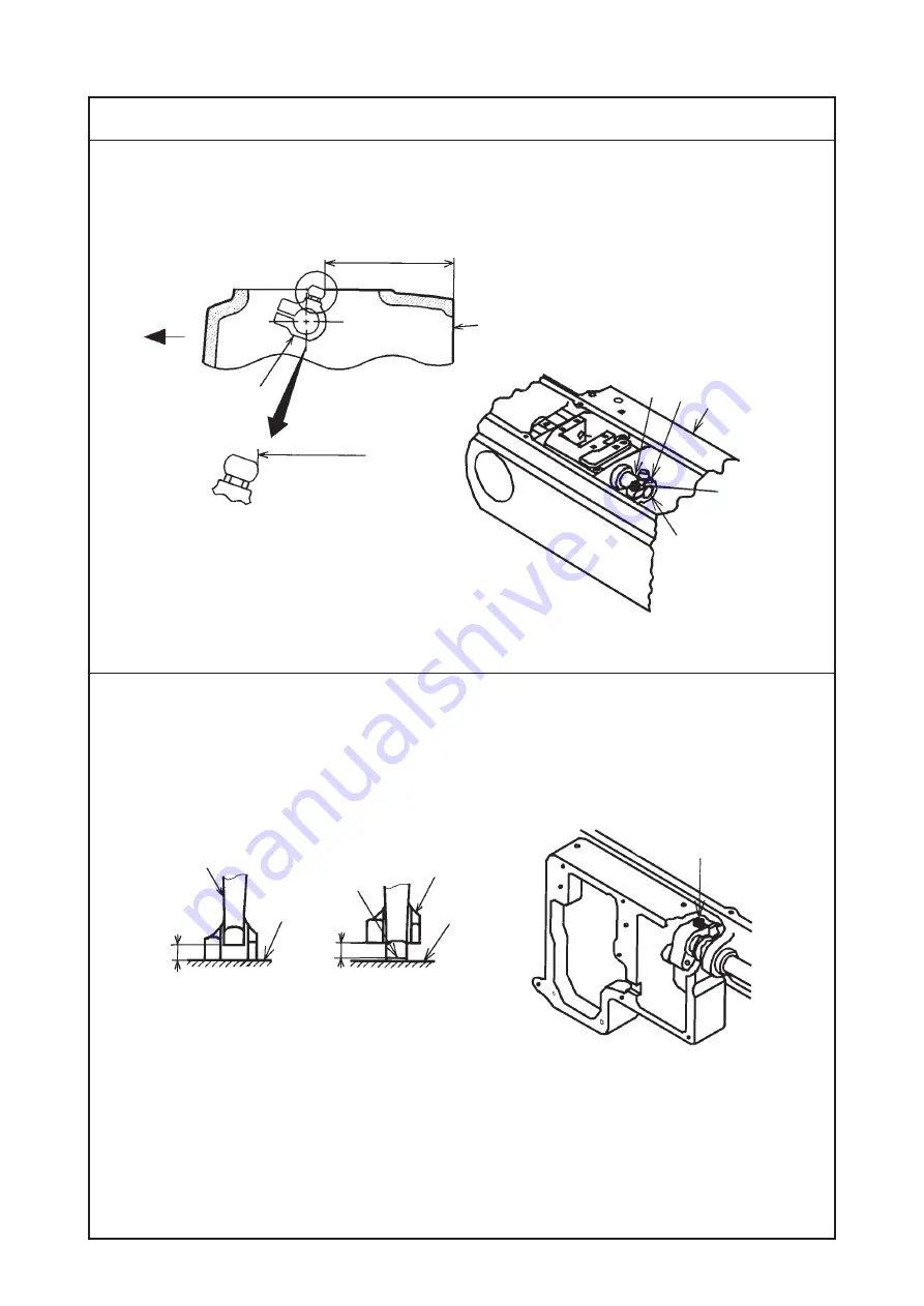
(11) Feed motion

1) Amount of alternate vertical movement (position of the vertical adjusting arm)

1

2

2) Alternate momentum

1

2

3

A

B

Top surface of

feed dog

Top surface of
throat plate

Top surface of
throiat plate

Conditions
• Feed amount : 0 mm
• Amount of alternate vertical movement : standard

1

4

3

73 to 74 mm

Operator’s
side

Edge of

machine arm

To align
with edge

73 to 74 mm

Summary of Contents for LU-1520N-7

Page 1: ...wheel Motor Specifications LU 1520N 7 1 needle unison feed lockstitch machine with automatic thread trimmer Needle thread roll in and shorter thread remaining type For heavy weight materials Max 3 000 rpm SCHMETZ 135 X 17 Nm 125 to 180 Standard Nm 160 30 to 5 30 to 5 Max 9 mm normal reverse feed Hand lifter 9 mm Knee lifter 16 mm By dial Air cylinder type with touch back switch Slide thread take u...

Page 2: ...DJUSTMENT 1 Needle entry position 1 2 3 2 60 mm Top surface of throat plate Conditions Needle bar at lowest dead point Feed amount 0 mm Conditions Needle bar at lowest dead point Feed amount 0 mm A Clearance between the feed dog and the throat plate when the feed amount is maximum and the feed dog travels fully to the front 1 3 a a A 1 8mm ...

Page 3: ...ly tensed stitches will result The throat plate comes in contact with the feed dog and contacting noise occurs and the throat plate or the feed dog may be damaged Irregular stitches may result 1 Set the stitch dial to 0 2 Turn the handwheel to bring the needle bar to the lowest dead point of its stroke 3 Loosen clamping screw 3 in the feed rocker 4 Move the feed base and adjust so that needle 1 en...

Page 4: ...d dog 3 Lateral position of the feed dog 1 2 1 2 3 4 a a A B A Conditions Needle bar at lowest dead point Feed amount 0 mm Conditions Feed amount 0 mm Height of feed dog is maximum Model Dimension A LU 1520N 7 0 4 to 0 5 mm Adjust the position to almost A B 3 a a ...

Page 5: ...n the scale of the feed dial Balloon stitches will result Return of sewing product will occur Feed dog comes in contact with the knife and the knife and the feed dog may be damaged When the height of the feed dog is lower than the specified value Stitch pitch becomes smaller than the scale of the feed dial Feed force will be deteriorated Stitch skipping or thread breakage will result Poorly tensed...

Page 6: ...er hook guide 5 Height of the hook Conditions When the inner hook guide travels to its back end Press the inner hook stopper to the groove in the throat plate 1 2 3 4 3 0 1 to 0 2 mm B Hook stopper section 4 1 0 1 mm 1 2 3 To come in close contact with each other ...

Page 7: ...section should align with No 1 screw of setscrews 1 When the clearance is larger than the specified value Loose stitches or thread breakage will result When the clrarance is smaller than the specified value Inner hook or inner hook guide may be damaged Stitch skipping or thread breakage will result Needle breakage will result Irregular stitches will result 1 Turn the handwheel to bring inner hook ...

Page 8: ...le bar rises from the lowest dead point of its stroke 6 Model Dimension B Dimension C Dimension D LU 1520N 7 2 3 0 2 mm 1 5 0 2 mm 0 05 to 0 1 mm A 4 4 8 3 5 6 7 5 Standard of dimension B Engraved marker line on the lower side of needle bar B C D 0 1 to 0 2 mm Standard Engraved marker line on the upper side of needle bar ...

Page 9: ...saddle Then move the hook driving shaft saddle to the right or left to adjust the cearance between needle 5 and blade point 6 of the hook to dimension D Then securely tighten setscrew A 4 and setscrew B 8 4 Turn the handwheel and move the screw gear large to the right or left so that needle 5 aligns with blade point 6 of the hook when needle bar 1 is raised from the lowest dead point of its stroke...

Page 10: ...er foot 1 Hand lifter 1 2 9 0 3 mm Top surface of throat plate Condition State that the hand lifter is raised Standard Adjustment 2 Automatic presser foot lifter 16 0 5 mm Top surface of throat plate 1 2 3 4 0 5 to 1 5 mm B A ...

Page 11: ...ount is lower than the specified value The presser foot is not sufficiently raised and the working property may be deteriorated 2 Automatic presser foot lifter 1 Loosen cylinder nut 1 and adjust the screwing amount of cylinder connecting screw 2 so that the height from the top surface of the throat plate to the bottom surface of the presser foot becomes 16 0 5 mm Turn in the direction A Lifting am...

Page 12: ...iming 9 Timing between the upper shaft and the lower shaft 1 Horizontal feed cam timing 1 2 3 4 1 2 3 To be level Conditions Feed amount 0 mm Needle bar at lowest dead point Screw No 1 Main shaft Conditions Feed amount maximum Needle bat at lowest dead point ...

Page 13: ...e stitch dial to the maximum 2 Loosen two setscrews 1 in the horizontal feed eccentric cam 3 Turn the handwheel to bring the needle bar to the lowest dead point of its stroke 4 Turn feed eccentric cam 2 and adjust the timing so that the feed dog no longer moves even when the reverse feed control lever is moved 5 Securely tighten two setscrews 1 in the horizontal feed eccentric cam Standard The set...

Page 14: ...ice is not provided When DL device is provided Standard Adjustment 1 3 4 5 Main shaft Top feed cam rod To align Conditions Feed amount 6 mm When needle and walking foot are lowered Top feed cam rod 2 Top feed cam rod Screw No 1 Screw No 1 ...

Page 15: ...ace are aligned with one another on condition that the amount of alternate vertical movement of both the walking foot and the presser foot is equal 6 Securely tighten two setscrews 1 in the top feed cam Standard Screw No 2 of top feed cam 5 faces just above and screw No 1 of top feed cam 5 faces to the direction of the arrow when needle tip 2 and walking foot 4 align with top surface 3 of the thro...

Page 16: ...ertical adjusting arm 1 2 2 Alternate momentum 1 2 3 A B Top surface of feed dog Top surface of throat plate Top surface of throiat plate Conditions Feed amount 0 mm Amount of alternate vertical movement standard 1 4 3 73 to 74 mm Operator s side Edge of machine arm To align with edge 73 to 74 mm ...

Page 17: ...the amount of alternate vertical movement of walking foot 1 and presser foot 2 is almost equal 3 When the amount is not equal loosen setscrew 3 in the top feed rear arm and adjust so that the amount should be equal Adjust the amount almost to A B When the amount of alternate vertical movement of the walking foot is larger than that of the presser foot 1 Loosen setscrew 3 in the top feed rear arm i...

Page 18: ...way Adjusting the bottom feed amount 1 2 3 20 0 5 mm Horizontal feed shaft Engraved marker line Standard Adjustment 13 Stitch length of normal reverse feed 1 2 A B Feed adjusting base Notch Feed adjusting rod Conditions Feed amount 6 mm ...

Page 19: ...reased Caution When you desire to change the bottom feed amount re adjust the needle entry position since the needle entry position changes Adjustment Procedures Results of Improper Adjustment 1 Set the stitch dial to 6 2 Loosen two setscrews 1 in the feed adjusting eccentric pin 3 Turn feed adjusting eccentric pin 2 to adjust the stitch length Direction A reverse feed pitch is increased Direction...

Page 20: ...stment 14 Position of the reverse feed control lever 1 2 3 1 0 5 m m 3 Feed regulator Reverse feed lever shaft Standard Adjustment 15 Safety clutch 1 2 A B 4 1 Standard of release pressure 3 1 3 2 24 5N m 9 8N m 5 9N m ...

Page 21: ...ewing When the safety clutch functions the hook will not rotate even if turning the handwheel and the hook driving shaft sprocket wheel only will run idle since the power is not transmitted to the hook driving shaft Resetting procedure 1 Checking the moving part of the sewing machine and look for and remove the cause which the safety clutch has functioned 2 Pressing push button 1 located on the to...

Page 22: ... 22 Standard Adjustment 16 Reverse feed cylinder and condensation cylinder Standard 8 to 8 5 mm 1 2 3 4 5 6 7 8 7 to 8 mm Feed adjusting rod Hinge screw ...

Page 23: ...Tighten nut 7 5 Install cylinder 5 on window plate 6 with two setscrews 4 Confirmation 1 Actually perform sewing 2 Check that the stitch length of one stitch before thread trimming is 1 5 to 2 mm of reverse feed stitching When the fork section does not enter the hinge screw stitches of the reverse feed may not be obtained When the distance from the cylinder to the cylinder screw is smaller than th...

Page 24: ... 24 Standard Adjustment 17 Lubrication A sheet of paper 1 2 3 A 4 5 1 6 7 8 9 0 1 2 3 4 2 3 Decrease Increase B ...

Page 25: ...nce a month clean the oil tank 1 and the filter case 2 If the filter 3 is clogged with soil lubrication fails resulting in trouble Cleaning the oil tank 1 Remove the oil pipe 2 from oil tank 1 2 Remove butterfly nut 6 and take out cover upper 7 filter 8 and cover lower 9 to clean the oil tank 3 Remove filter case setscrews 0 and clean filter element 1 located on the inside of the filter case and m...

Page 26: ...immer device 1 Lateral position of the thread trimmer base Standard Adjustment Left end of throat plate 1 2 3 4 5 6 7 8 1 To align both ends Condition Thread trimmer base aligns with end of machine bed 20 0 to 20 5 mm ...

Page 27: ...ndwheel in the state that cam roller 8 is located in the groove of thread trimmer cam 7 and adjust the needle bar to the upper dead point of its stroke 5 Advance moving knife 5 and check that moving knife 5 does not interfere with the inner hook 6 Return moving knife 5 and waiting knife 6 to the respective initial positions and connect the air hose to the regulator When the distance from the movin...

Page 28: ... 28 2 Height of the moving knife Standard Adjustment Bottom surface of throat plate Throat plate 3 Knife pressure 1 2 3 4 3 0 35 0 1 mm 1 2 3 4 9 t o 1 0 m m ...

Page 29: ...ing failure of thread trimming single thread trimming or defective clamp may occur 1 Remove the air hose connecting to the regulator and cut off the air 2 Loosen setscrews 1 in the clamp spring base so that the clamp pressure is not applied to moving knife 3 3 Loosen setscrews 2 in the moving knife base 4 Move moving knife base 4 up or down so that the distance from moving knife 3 to the bottom su...

Page 30: ...rive shaft To come in close contact with each other 0 1 to 0 2 mm Conditions Moving knife Moving knife drive arm 2 should come in close contact with drive arm stopper 3 Waiting knife Clearance provided between waiting knife drive arm B 6 and drive arm stopper 3 is 0 1 to 0 2 mm End of machine bed Long hole To come in close contact with each other 26 4 0 2 mm ...

Page 31: ... the regulator and cut off the air 3 Raising upward knife fixing plate 8 advance moving knife 4 and waiting knife 9 by hand 4 Check that cam roller 1 lightly enters the groove of thread trimmer cam 0 Standard Lower end plane of waiting knife drive arm B 6 aligns with that of the waiting knife shaft 5 Return moving knife 4 and waiting knife 9 to the respective initial positions and connect the air ...

Page 32: ...nife End of machine bed 1 2 3 4 5 6 7 8 7 8 To come in close contact with each other Hook driving shaft front bushing Standard Approx 0 5 mm To come in close contact with each other Condition Screw should come in close contact with moving knife drive arm 1 mm 0 0 5 ...

Page 33: ...nd adjust screw 3 so that the distance from the top end of moving knife 2 to the end of machine bed is 1 mm At this time screw 3 should come in close contact with moving knife drive arm 4 7 Tighten nut 1 Adjustment Procedures Results of Improper Adjustment When the distance from the top end of moving knife to the end of machine bed is larger than the specified value Failure of needle bobbin thread...

Page 34: ...vanced position of the waiting knife and the cam timing Condition Thread trimmer cam should come in close contact with end of cam roller Standard Approx 0 5 mm Hook driving shaft front bushing To come in close contact with each other 0 4 0 2 21 mm ...

Page 35: ...g shaft front bushing is approximately 0 5 mm Cam timing 1 Make the end of the groove of thread trimmer cam 3 come in close contact with cam roller 4 in the state that waiting knife 2 is in the most advanced position 2 Align the red engraved marker dot on the handwheel with the engraved marker dot on the machine arm 3 Tighten two setscrews 1 When the distance from the top end of waiting knife to t...

Page 36: ... 36 Standard Adjustment 7 Position of the clamp spring Thread trimmer base 1 2 3 4 5 2 3 24 3 0 1 mm 28 3 0 2 mm To come in close contact with each other To come in close contact with each other ...

Page 37: ...mp pressure 1 Loosen setscrews 1 2 Move clamp spring base 2 in the direction of the arrow by approximately 0 5 mm from the state that clamp spring 3 comes in contact with moving knife 5 Clamp spring base 2 should come in close contact with the end of the thread trimmer base 3 Tighten setscrews 1 When the clamp spring is located in the front Clamp spring interferes with the moving knife to cause th...

Page 38: ...f sewing device 22 to 23 mm When cylinder shaft is stretched 2 Thrread presser device Standard Adjustment 1 Threading device A 2 94N or more 1 2 3 4 5 6 A 1 0 5 mm Standard 5 5 to 6 5 mm When cylinder shaft is shrunk Tetoron thread 8 1 2 3 B ...

Page 39: ...ovided between the threading plate and the end of machine arm is larger than the specified value Threading plate comes in contact with the thread take up As a result breakage will result When the clearance provided between the threading plate and the end of machine arm is smaller than the specified value Threading plate comes in contact with machine arm As a result breakage will result When the di...

Page 40: ...een White Black Amount of alternate vertical movement of the walking foot and presser foot Less than 2 5 mm 2 5 mm to less than 4 mm 4 mm to less than 4 75 mm 4 75 mm to less than 6 5 mm Stitch length 6 mm or less 3000 rpm 2400 rpm 2000 rpm 1800 rpm Stitch length More than 6 mm and 9 mm or less 2000 rpm 2000 rpm 2000 rpm 1800 rpm Scale of alternate vertical dial 1 to 2 5 2 625 to 4 4 125 to 4 75 4...
Page 41: ...inner diameter of the bushing to the edge of the switch body to 8 0 1 mm Then tighten installing screws 2 of the detection switch of the amount of alternate vertical movement 4 Adjust the scale 1 to the convex section on the top cover place the pin and the spring in the hole of section A install the alternate vertical dial and tighten setscrew 1 in the alternate vertical dial Caution When the posi...

Page 42: ... support 5 to the machine arm with setscrews 4 7 When installing window plate F 7 enter alternate vertical link hinge screw 5 to the hole of alternate vertical link 2 and attach it to the machine arm 8 Re adjust the respective timing adjustment referring to this manual 9 Remove plate 7 attached to pneumatic device asm A being used now and assemble solenoid valve B 8 10 Connect the solenoid valve p...

Page 43: ...aforementioned parts has been forced to be disassembled be sure to wash the LOCKTITE applied part using a paint thinner or the like and reassemble it using LOCKTITE after removing any moisture from the mating faces If it is hard to remove a part which has been fixed using LOCKTITE heat it using a torch lamp or the like to help remove the part No 1 No 2 No 3 No 4 No 5 No 6 Thread release bar LOCKTI...

Page 44: ...03 2 t 1 2 mm Ditto 10111102 3 t 1 3 mm standard Ditto 10111201 4 t 1 4 mm Ditto 10109809 5 t 1 5 mm Ditto 10112506 6 t 1 6 mm Ditto 10102605 7 t 1 7 mm Ditto 10102704 8 t 1 8 mm Name of consumable part Part No Remarks Needle MC372001600 SCHMETZ 135 X 17 Nm 160 Hook asm 21393756 Bobbin 21334800 Aluminum bobbin with knurl Moving knife 21395801 Waiting knife 21395900 Clamp spring 21396007 ...

Page 45: ... ON THE HANDWHEEL 7 LUBRICATION ROUTE DIAGRAM Range of needle up stop position white Needle up stop position at the time of reverse revolution to lift needle Adjustment of thread trimmer cam red Needle down stop position yellow ...

Page 46: ...trimmer Threading thread presser Threading Presser lift Presser lift DL Knife fixing Indication No 1 2 3 4 5 6 7 8 9 A Remarks Cylinder pull in side Cylinder push out side Cylinder push out side Cylinder pull in side Cylinder pull in side Cylinder push out side For DL device only 1 2 3 4 5 6 7 8 9 1 2 3 4 5 6 7 8 9 A 5 A ...

Page 47: ...hreading switch Threading switch Pin No 1 2 Remarks HTSW White GND Black Name of part Detection switch Detection switch Detection switch Detection switch Pin No 1 2 3 4 Remarks 12V Red LED Blue SW Yellow GND Orange Name of part 5 string switch 5 string switch 5 string switch 5 string switch 5 string switch 5 string switch 5 string switch 5 string switch 5 string switch Pin No 1 2 3 4 5 6 10 13 14 ...

Page 48: ...r DL type only 6 pin connector Name of part Solenoid valve 2 Solenoid valve 2 Solenoid valve 3 Solenoid valve 3 Solenoid valve For AE 10 Solenoid valve For AE 10 Pin No 3 4 1 2 5 6 Remarks Threading Red Threading Black Thread trimming Red Thread trimming Black Air nozzle Red For AE 10 type only Air nozzle Black For AE 10 type only 3 Connectors coming from the relay cable Connecting side to the con...

Page 49: ...2 13 14 15 Relay cable A asm GND Black DL switch 1 Red DL switch 2 White 24V Black IN2 Black GND White Threading AE 10 Yellow AE 10 Blue OUT7 Black OUT6 Red Threading Orange Relay cable B asm AK Black AK White 15 pin connectot 6 pin connector Pin No 1 2 3 4 5 Relay cable A asm INA White 12V Red CKU Black Relay cable B asm INA White 12V Red INB Black CKU Black 2 pin connector Pin No 1 2 Relay cable...

Page 50: ... trimming OFF timing 122 LS Tension release ON timing 180 L2 Tension release OFF timing 20 When thread trimming failure occurs change the value of TS At this time change the value of TE as TS TE 186 as well Thread trimming signal DOWN position UP position Sewing machine Thread trimming solenoid valve output Tension release solenoid output Condensation solenoid valve output Threading switch input T...

Page 51: ...rts Check the clearance Check the clearance Check the amount of oil in the hook Check the specified dimension Check the amount of oil in the hook Remove the sharp edges or burrs on the blade point of hook using a fine emery paper Buff up the groove section on the throat plate Adjust the needle thread tension Refer to 7 Needle to hook timing Decrease the clearance Refer to 6 Adjusting the inner hoo...

Page 52: ...pecified dimension Check the pressure of the presser foot Check the lowest point of the needle bar Check the blade point of the hook Check the functional amount of the needle guard Refer to 7 Needle to hook timing Refer to 7 Needle to hook timing Tighten the presser spring regulator Refer to 7 Needle to hook timing Correct the blade point of the hook or replace the hook Replace the needle with one...

Page 53: ...e thread paths Check the change of bobbin thread tension Walking foot is not of top divided type Compare the height with the standard value Refer to 6 Adjusting the inner hook guide Finish using a fine emery paper or buff Replace the bobbin or the hook Use the optional walking foot and presser foot Refer to 4 Height of the feed dog Lower the height by 0 2 mm than the standard value Retard the feed...

Page 54: ...d tension Check the state of bobbin winding Check the setting Adjust the thread take up spring to move to approximately 1 mm from the initial position when hook draws thread maximumly Finishwithafineemerypaperorbuff Replace the bobbin or the hook Increase the tension of the bobbin thread Decrease or increase the tension applied to the bobbin winder Properly set the bobbin Troubles Causes Checking ...

Page 55: ...ng Position of the clamp spring Pressure of the clamp spring is too low There are scratches on the clamp spring Needle thread removes bobbin thread Thread the needle thread correctly Adjust so that abnormal needle thread tension is not applied Decrease the tension given by the tension controller No 1 Adjust so that the disk is raised by means of the thread release solenoid Refer to 10 TIMING CHART...

Page 56: ...justed The blades of moving knife and waiting knife have wom out or broken Thread trimming timing is excessively retarded Pressure of the waiting knife is insufficient Presser foot drops from cloth at the time of thread trimming Thread is too thick Thread trimming timing is excessively retarded Needle thread tension is too high Refer to the Cause Needle thread remaining at the needle top afer thre...

Page 57: ...s broken or been scratched Checktheheightofmoving knife Presser foot drops from cloth at the time of thread trimming Adjust the tension of bobbin thread Refer to 18 3 Knife pressure Refer to Causes Thread cannot be trimmed and Thread remains uncut after trimming Perform thread trimming on cloth Refer to 7 Needle to hook timing Refer to 16 Reverse feed cylinder and condensation cylinder Refer to 18...

Page 58: ... Moving knife fails to work Presser foot drops from cloth at the time of thread trimming Refer to 18 3 Knife pressure Refer to 18 3 Knife pressure Adjust the synchronizer timing Refer to 18 6 Most advanced position of the waiting knife and the cam timing Air pressure is excessively low Adjust the air pressure Adjust it to 0 5 Mpa or more Perform thread trimming on cloth Turn ON the threading switc...

Page 59: ... R22 5 4 R 8 R 1 0 R 1 0 4 R 2 1 5 4 R 2 2 5 R 1 0 R 1 0 R2 C 1 535 C 1 S W W Y S W W X X V V Y Y Y V V 1 1 W W 1 1 X X 1 1 S S Z Z 11 0 8 0 8 5x160 600 120 Thickness 1 5 Thickness 1 5 Thickness 0 5 Thickness 0 8 0 5 7 5 7 5 11 5 7 Style of tpe Helvetica Reg Condensed Condensed voided letters Dimension drawing in detail 1 2 3 4 5 6 7 8 9 1 4 ø3 4 Depth 10 Drill a hole at the time of set up 2 Insta...

Page 60: ...R ENGINEER S MANUAL 29359502 No E351 00 1 needle Unison feed Lockstitch Machine with Automatic Thread Trimmer Needle thread roll in and shorter thread remaining type LU 1520N 7 ...

Page 61: ...edures Results of Improper Adjustment and other important information which are not covered in the Instruction Manual It is advisable to use the relevant Instruction Manual and Parts List together with this Engineer s Manual when carrying out the maintenance of these machines This manual gives the Standard Adjustment on the former page under which the most basic adjustment value is described and o...

Page 62: ...16 12 Needle sway Adjusting the bottom feed amount 18 13 Stitch length of normal reverse feed 18 14 Position of the reverse feed control lever 20 15 Safety clutch 20 16 Reverse feed cylinder and condensation cylinder 22 17 Lubrication 24 18 Thread trimmer device 26 1 Lateral position of the thread trimmer base 26 2 Height of the moving knife 28 3 Knife pressure 28 4 Initial position of the moving ...

Page 63: ...LE PARTS 44 6 ENGRAVED MARKER DOTS ON THE HANDWHEEL 45 7 LUBRICATION ROUTE DIAGRAM 45 8 PNEUMATIC COMPONENTS PIPING 46 9 MACHINE HEAD WIRING 47 1 Connectors coming from machine head 47 2 Connectors coming from the pneumatic device 48 3 Connectors coming from the relay cable Connecting side to the control box 48 10 TIMING CHART 50 11 TABLE OF TROUBLES AND CORRECTIVE MEASURES 51 1 With reagard to se...

Page 64: ...n this engineer s manual is subject to change for improvement of the commodity without notice 02 05 Printed in Japan E R INTERNATIONAL SALES H Q 8 2 1 KOKURYO CHO CHOFU SHI TOKYO 182 8655 JAPAN PHONE 81 3 3430 4001 to 4005 FAX 81 3 3430 4909 4914 4984 TELEX J22967 Copyright C 2002 JUKI CORPORATION All rights reserved throughout the world ...

Reviews: