

TO INSERT WELDING FILTER:
Remove the inner securing frame and
one of the two protective clear lenses from the faceshield. Insert the
welding filter, followed by the clear lens and securing frame, ensuring that
the inner frame clicks firmly into place.
FITTING
FOR HARNESS MOUNTED FACESHIELD:
The head height and size can be adjusted as follows:
1.
Slide left half of crown strap through loops on the right half to obtain
correct height, engage retaining pin in correct hole.
2.
Place faceshield on head and check height setting. Ensure headband
is not too low on brow. If necessary repeat step 1 until correct height
adjustment is achieved.
3.
With faceshield on head turn adjuster knob to obtain a firm and comfortable fit.
FITTING
FOR HELMET MOUNTED FACESHIELD:
The faceshield is designed to be fitted to most leading makes of industrial
safety helmet with standard size peak. Slide helmet peak into slot in the
faceshield. Stretch PVC covered retaining spring over the crown of the
helmet until it fits securely around the helmet shell.
USE:
The faceshield will only offer protection with a welding filter correctly
inserted and when the faceshield is in the lowered position. The welding
filter is marked with the appropriate shade grade. For proper selection of
the filter grade please consult the chart. Ensure that the correct welding
filter is fitted before commencing welding operations.
Toughened mineral filter oculars shall only be used in conjunction with a
suitable backing ocular.
The scale number, given in the table below, is to be used for arc welding,
gas welding and arc gouging. The following abbreviations are used
according to ISO4063:
• MIG corresponds to Metal Arc Welding with Inert Gas Shield.
• MAG corresponds to Metal Arc Welding with Non-inert Gas Shield.
• TIG corresponds to Tungsten Inert Gas.
• Arc-Air Gouging corresponds to the use of a carbon electrode
and a compressed air jet to remove the molten metal.
The term ‘heavy metals’ applies to steels, alloy steels, copper and its
alloys, etc. The hatched areas correspond to the ranges where the welding
operations are not usually used in the current practice of manual welding.
Note:
If the use of filters selected from the table produces a feeling of
discomfort, the working environment and the eyesight of the operator
should be examined. It can be harmful to use filters with too high a scale
number (too dark) as this would force the operator to move too close to
the radiation source and to inhale harmful fumes. For work carried out
in the open air and strong natural light, it is possible to use a filter one
scale number higher.
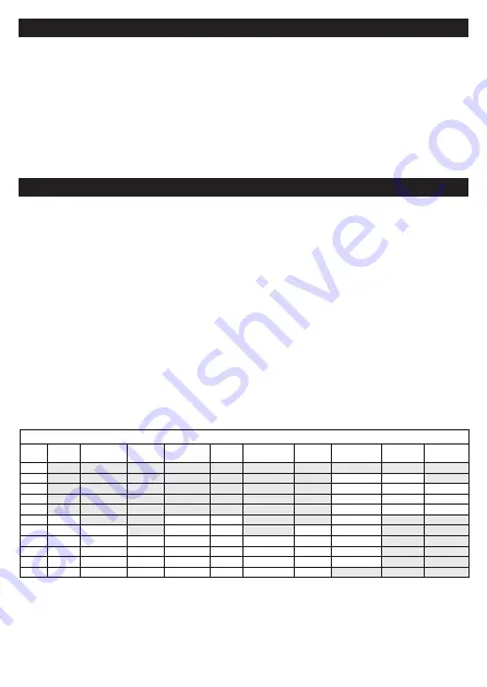
In the table the letter A corresponds to the current rating of the welding
device in Amperes. The letters l/h correspond to the flow rate of the
acetylene gas in litres per hour.
Welding Process or Related Technique
Scale
Number
Covered
Electrode
MIG with
heavy metals
MIG
light alloys
TIG on all
metals/alloys
MAG
Air-arc gouging
Plasma jet
cutting
Microlasma arc
welding
Gas welding Gas cutting
3
4
1.5-6A
<70l/h
5
6-15A
70-200l/h
900-2000l/h
6
15-40A
200-800l/h 2000-4000l/h
7
40-60A
>800l/h
4000-8000l/h
8
<60A
10-30A
<70A
60-100A
9
60-100A
70-125A
30-70A
70-100A
100-125A
100-125A
10
100-150A 125-175A
125-175A
70-125A
100-150A
<175A
125-150A
125-175A
11
150-200A 175-250A
175-225A
125-200A 150-225A
175-200A
150-175A
175-225A
12
200-300A 250-350A
225-300A
200-300A 225-400A
200-250A
175-250A
225-325A
13
300-450A 350-450A
300-400A
300-350A 400-600A
250-350A
250-400A
IMPORTANT NOTE:
This table is for guidance only. It is the USERS responsibility to ensure that Protective Equipment is suitable and adequate for use
in the intended hazardous environment.
FITTING & USING WELDING FACESHIELD
VISOR REPLACEMENT:
Scratched or damaged visors should be replaced. Replacement visors are
available for all faceshields. Under normal circumstances the faceshield and
visor should offer adequate protection for 2–3 years.
I
NVINCIBLE & CLIPTITE:
1.
Pull visor off press-studs at each end.
2.
Disengage visor from centre peg.
3.
Reverse procedure to fit new visor.
FACESAVER & MARTCARE:
1. Push out and retain stud securing visor to browguard.
2.
Swing visor down and disengage visor keyhole slots from either side of browguard.
3.
Reverse procedure to fit new visor
SUREFIT™:
1.
To remove the old visor, press the top of it inwards so it comes away from
pip and pull down. Repeat for other two pips.
2.
Locate the new visor into the channel around the rim of the visor carrier.
3.
Push the centre of the visor inwards in order to locate the central hole over
the central pip of the visor carrier.
4.
Ensuring the visor is located in the channel on the relevant side locate the
remaining two pips.
LITEGUARD™:
1. To remove the old visor, press the top of it inwards so it comes away from notch.
2. Swing visor down and disengage visor keyhole slots from either side of browguard.
3. Reverse procedure to fit new visor.
VISOR REPLACEMENT FOR CLEAR & WIRE GAUZE VISORS


