JRC NJJ-105 Handy Search User Manual Download Page 37


- 26 -


2.4 CF Control screen 

While scanning is in off status and the   12   

CF

 key is pressed, the screen switches to the CF 

control screen and CF memory control can be performed. To return to the scan screen, press the  

12  

CF

 key once more. See Sections 3.6.2 to 3.7.4 for how to control the CF memory. The CF 

control screen is shown in Figure 2-9. 


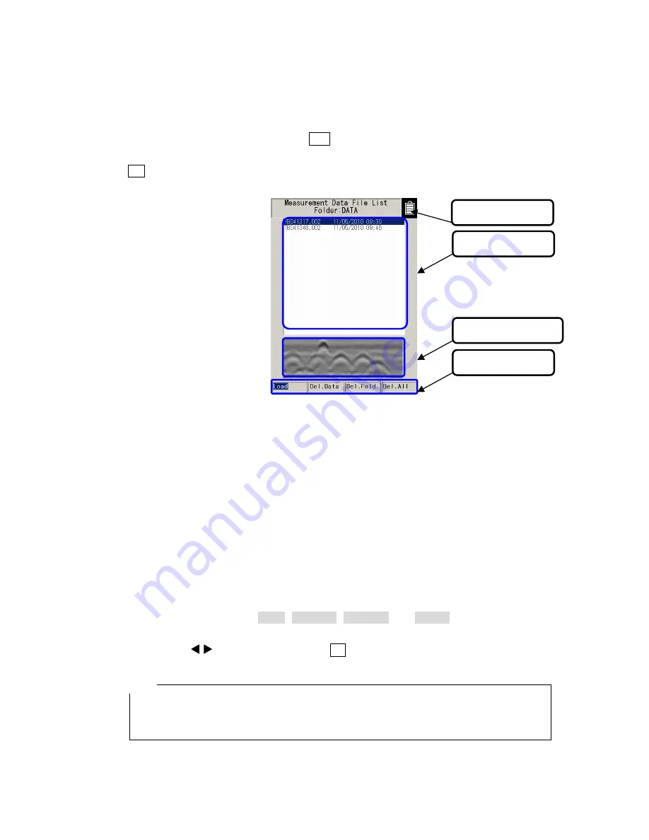
Figure 2-9    CF Control Screen 

(1) Title 

Displays the folder name accessed on the CF memory. To change the accessed folder, see 

Section 2.3.9 Folder. 


(2) File 

selection 

Displays the file names for data saved on the CF memory. To select a file, move the cursor 

(inverse video line) on the desired file by pressing the 

▲▼

 cursor keys. 


(3)  Thumbnail image display 

Displays the scan result stored in the file selected in (1) as a thumbnail. 


(4) Control 

functions 

Displays control functions ( Load ,    Del.Data ,    Del.Fold. , and    Del.All ) for the CF memory. To 

select and execute a function, move the cursor (inverse video line) on the desired function by 
pressing the 

  cursor keys and press the    5   

ENTER

 key. 


  The thumbnail displays a part of the selected file (Distance direction; around 0.5 m, 

depth direction: around half of the display range). The image processing selected at 
the image processing setting is applied to the thumbnail image. 


(2) File selection 

(3) Thumbnails 

(4) Control items 

Remarks 

(1) Title 

Summary of Contents for NJJ-105 Handy Search

Page 1: ...Handy Search Users Guide...

Page 2: ...inforcing steel bars in reinforced concrete structures Before starting to use the NJJ 105 Handy Search read through this instruction manual carefully to learn correct operations and ensure correct and...

Page 3: ...ompactFlash CF is a registered trademark or SanDisk Corporation WARNING This indication is shown where any person is supposed to be in danger of being killed or seriously injured if this indication is...

Page 4: ...r plug by wet hands Doing so could cause an electric shock Do not use place this product in a location where it is exposed to flammable or corrosive gas Doing so could cause fire personal injury or br...

Page 5: ...o not use place this product in a location where it is subject to vibration or shock Doing so may cause a personal injury or breakdown When loading unloading printing paper be careful not to cut or ja...

Page 6: ...v Appearance...

Page 7: ...en 12 2 2 1 Scan screen example during scanning 12 2 2 2 Scan screen example during not scanning 14 2 3 Parameter setting screen 16 2 3 1 disp color 16 2 3 2 disp direction 16 2 3 3 disp mode 17 2 3 4...

Page 8: ...n while not Scanning 41 3 3 1 Mode switching 41 3 3 2 Sensitivity switching 42 3 3 3 Cursor operation 42 3 4 Image Processing 48 3 4 1 Fixed surface wave processing 48 3 4 2 User surface wave processi...

Page 9: ...76 3 10 2 Charging Device BC 3008 series 78 4 Theory 79 4 1 Principle of Operation 79 4 2 Applicable Conditions 80 5 Maintenance Inspection 81 5 1 Daily Inspection 81 5 2 Daily Maintenance 81 5 3 Tro...

Page 10: ...aves reflected from the concrete surface by using the internal fixed surface wave data and shows only the reflected wave from rebar etc User surface wave processing Image processing to remove the unwa...

Page 11: ...s of this product Time feed scan Scan method that performs B mode scanning at preset time intervals regardless of movement of this product Relative dielectric constant Object specific coefficient The...

Page 12: ...ult with no consideration of the depth sensing capability may cause the accidental cutting of rebar 1 1 Function Table 1 1 shows functions and performances of this product Table 1 1 Functions and Perf...

Page 13: ...essing After scanning Fixed surface wave processing User surface wave processing Deduction processing Manual surface wave processing Average wave processing Peak processing and Original image 10 Depth...

Page 14: ...ve reflection Even if scanning is performed above rebar that is parallel to the scanning direction this product can still detect any rebar that is crosswise to the scanning direction 3 Obtaining conti...

Page 15: ...h a new sensitivity setting is not necessary 10 A marker can be displayed in the scan results using the cursor marker function A maximum of 42 cursor markers can be placed in the scan results to displ...

Page 16: ...n to the standard components Table 1 3 Options Name Model Number Remarks Battery charger set for the Handy Search 1 CBK 154 For the battery pack BP 3007 series Set configuration Adapter PWC L07 series...

Page 17: ...agram Figure 1 1 shows the overall system diagram of this product Figure 1 1 Overall System Diagram LCD CPU Memory Distance Detector Opkey Control section IrDA Trans CompactFlashmemory Trans Receive R...

Page 18: ...7 1 5 Configuration Figure 1 2 shows the external views of this product Figure 1 2 Handy Search NJJ 105 external dimensions diagram Top view drawing 64 79 4 147 Side view drawing 216 149...

Page 19: ...8 2 Parts Names and Functions 2 1 Handy Search NJJ 105 This section shows the operation panel of this product and explains the functions for each part Figure 2 1 Top View...

Page 20: ...key for start of image processing and various types of selection 6 PRCS Switch to image processing mode 7 None IrDAoptical receptor for communicating with the printer 8 None CF memory slot 9 START Sta...

Page 21: ...10 Figure 2 2 Side View Figure 2 3 Rear View...

Page 22: ...Rear Panel Number in Square Label Function 14 V Mark indicating the scan position 15 None Antenna face to radiate and receive electromagnetic waves 16 POWER ON OFF Turns power on and off 17 None Equi...

Page 23: ...setting screen See Section 2 3 6 depth to set the depth calibration value 2 Scan mode Displays the scan mode set at the parameter setting screen When selecting the distance feed scan m cm or mm is dis...

Page 24: ...marks See Section 3 2 4 Antenna mark for how to use the antenna mark 7 Distance gauge Displays the distance moved while performing a scan 8 Battery meter Displays the remaining power in the battery pa...

Page 25: ...isplayed When selecting Time feed scan s is displayed See Section 2 3 5 X axis to set the scan mode 3 Depth gauge Displays a search depth gauge The search depth gauge changes based on the depth calibr...

Page 26: ...ing screen See Section 2 3 11 disp range for the method to set the display range 11 Cursor marker coordinates Displays the coordinates of the cursor marker described in the item 6 above Below each of...

Page 27: ...s the 4 SET key again Regarding the operation to read out the scan data in CF memory see Section 3 7 2 Reading saved data Figure 2 6 Parameter setting screen 2 3 1 disp color You can specify the displ...

Page 28: ...een display direction Normal Screen display direction invert Figure 2 7 Screen display inversion 2 3 3 disp mode You can specify the display mode by this parameter The available settings are B and BA...

Page 29: ...as the absolute amplitude of the A mode waveform increases as shown in Figure 2 8 Abosolute value The offset uses the color gradation changing the drawing color between Black Indigo Green Yellow Red a...

Page 30: ...the actual relative dielectric constant of the concrete and the entered value the more the depth error Set an appropriate value to this parameter in accordance with the procedure described in section...

Page 31: ...in the CF memory by this parameter The file operation saving reading and deleting the scan data file is performed under the specified folder in the CF memory The available settings are DATA DATA02 DAT...

Page 32: ...stance correction constant When the distance correction constant is changed the scanning distance is also changed Adjust the distance correction constant by refering this scanning distance value The n...

Page 33: ...tting to this parameter in accordance with the procedure described in section 2 3 The XY unit setting is kept in the nonvolatile memory after turning off the product 2 3 14 Character Mode You can spec...

Page 34: ...ettting of this parameter changes automatically to NO 2 3 18 disp color setting You can specify the initial setting for disp color the display color at the power on by this parameter The available set...

Page 35: ...etting abs to the amplitude at the power on Set a desired setting to this parameter in accordance with the procedure described in section 2 3 2 3 22 X axis setting You can specify the initial setting...

Page 36: ...l setting for GAIN the sensitivity at the power on by this parameter The available settings are 2S 2 shallow 1S 1 shallow AS A shallow 1S 1 shallow 2S 2 shallow 2D 2 deep 1D 1 deep AD A deep 1D 1 deep...

Page 37: ...F memory To select a file move the cursor inverse video line on the desired file by pressing the cursor keys 3 Thumbnail image display Displays the scan result stored in the file selected in 1 as a th...

Reviews: