


OPTION 2: Remote Tail Lock and Rate Mode Access
( Available only with 8 and 10 channel systems)
Step 1: Locate the tail lock switch on the gyro amplifier and move to the ON posi-
t i o n .
Step 2: Verify that the mode remote select lead from the amplifier is connected to
the desired Aux channel Gear (Channel 5).
TAIL LOCK/ RATE MODE PROGRAMMING
Tail Lock Mode Programming (Option 2)
The programming shown below only applies if Option 2 was selected from the
p revious sections. The programming indicated in this section only applies to 8 and
10-channel systems.
If you have selected Option 1 Gyro Gain setting section.
JR 10 Series Systems
Step 1: Access a standard program mix (code 51-54) and assign a mix from Aux 3
(Ch 8) to Gear (Ch 5). This will make Aux 3 the master and Gear the slave channel.
P ress “E N T E R ” and select “N O ” for servo hold.
Step 2: P ress the “PA G E ” key to access the second screen. Select the desired flight
modes for the Tail Lock function to be active by pressing the “SEL” key below each
flight mode box as shown below.
In this example, we have selected flight modes 1 and 2 to be in tail lock mode. All
other modes, unless activated, will be set to the standard rate mode.
N o t e : For proper operation, please check to insure that all tail rotor mixing values
have been reset to 0 for the flight modes that tail lock mode will be used.
Step 3: P ress the “PA G E ” key again to re t u rn to the first screen. Set the mix value
located in the shaded box to - 100 as shown below.
Next, activate the
G550T and while
watching the LED indi-
cator on the amplifier,
move the flight mode
and throttle hold switch
t h rough their positions
to check that the
G550T is changing to
the desired modes (red for rate, green for tail lock).
If the G550T does not move to the desired modes, check to insure that the pro p e r
modes have been selected in the previous screen. If this information is correct, try
reversing the value in the shaded box from -100 to +100 and re t e s t .
On JR 10 series systems, please also check to insure that the gear switch has
been inhibited through
code 17 function
select. If the gear
switch is active, the
G550T will not change
modes correctly as
described.
JR 8103 Systems
Step 1: Access Program Mix 3 from the function mode and set the values as shown
in the screen at right.
Make sure the switch position (SW) is set to F-S12. This indicates that the mix
will be activated when the flight mode switch is moved to positions 1 or 2 only.
N o t e : For proper operation, check to insure that all tail rotor mixing values have
been reset to 0 for the flight modes that tail lock mode will be used.
Step 2: Tu rn the system O N, and while watching the LED indicator on the amplifier,
move the flight mode switch. The LED
should change from red (rate) to gre e n
(tail lock) as the flight mode switch is
moved. Set the rate or tail lock modes to
the desired flight modes. Our example
shows the selection of rate mode for
hover and throttle hold, and tail lock
mode for stunt modes 1 and 2.
GYRO GAIN SETTINGS
Adjust the gyro gain of your radio system as follows:
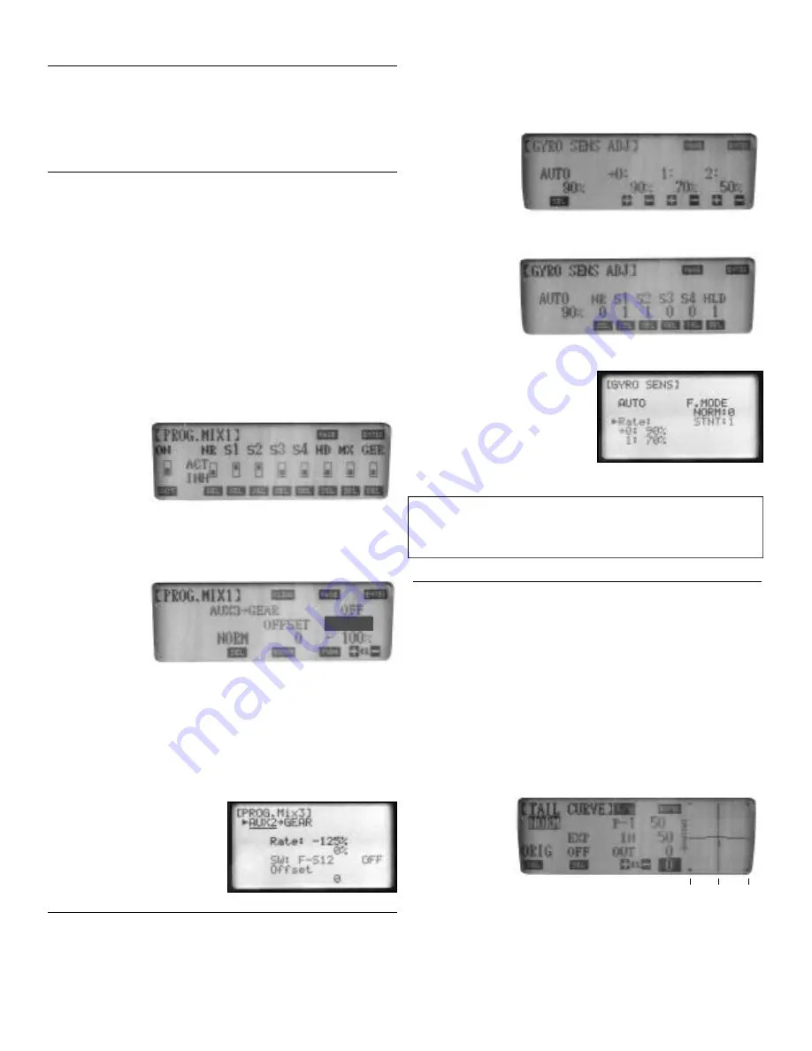
JR 10 Series systems
Step 1: Access the gyro gain function (code 44).
Step 2: P ress “SEL“ until “Auto” appears on the scre e n .
Step 3: Set the gain values as shown:
(please note that for this example, gain value 2 will not be used).
Step 4: P ress “PA G E ” and select the gain values for each flight mode as shown.
JR 8103 Series
Systems
Step 1: Access the
g y ro gain (Gyro Sens) function from the function mode.
Step 2: P ress the + or - key until “A U T O ” appears on the scre e n .
Step 3: Press “SEL”
twice and select the
following: NORM:0,
S T U N T: 1
Step 4: Set the gain
value as shown in the
s c reen at right.
All other radio systems (JR 622,642, 652, and non JR systems)
Step 1: Access the travel adjust function of
your system.
Step 2: C o n f i rm the gear switch position
as compared to the travel adjust values on
the screen and set the travel values for the
Gear channel (5) as follows:
Position 1 (Hover Gain): +90, Position 2
(Stunt Gain): -20
Step 3: Tu rn the system O N and verify that the gain value increased and decre a s e s
when the gain switch is moved.
N o t e : All gain values shown in this section are initial starting values only. Gain val-
ues can sometimes vary greatly due to the particular model, gear ratios, etc. Final
gain values can only be established after test flying. Please refer to the flight trim-
ming section of these instructions for more inform a t i o n .
TAIL ROTOR MIXING (RATE MODE ONLY )
Tail Rotor Mixing
While in rate mode, the G550T re q u i res a small amount of tail rotor mixing to
achieve maximum perf o rmance. tail rotor mixing should never be used with the
G550T in Tail Lock mode, as this mixing will cause the G550T to be unable to
achieve and locate the correct neutral position for the serv o .
N o t e : Due to the many variables involved with each diff e rent helicopter (engine,
blades, gear ratios, ro t o r, etc), the values shown are initial starting values only. Final
mixing values can only be achieved by test flying the model.
JR 10 Series Systems
N o rmal (Hover) Mode
PCM10/10S/10SX, 10SXII
N o rmal (Hover) Up 10% Down 10%
PCM10X
N o rmal (Hover)
Stunt (Flight) Mode
PCM10/10S/10SX
Stunt (Flight) Up +P4 Down -P4
PCM10SXII/10X
-6
0
-10
- 100%


