15. Alarm Message and Maintenance
15.1 Display of Alarm Message
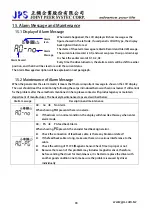
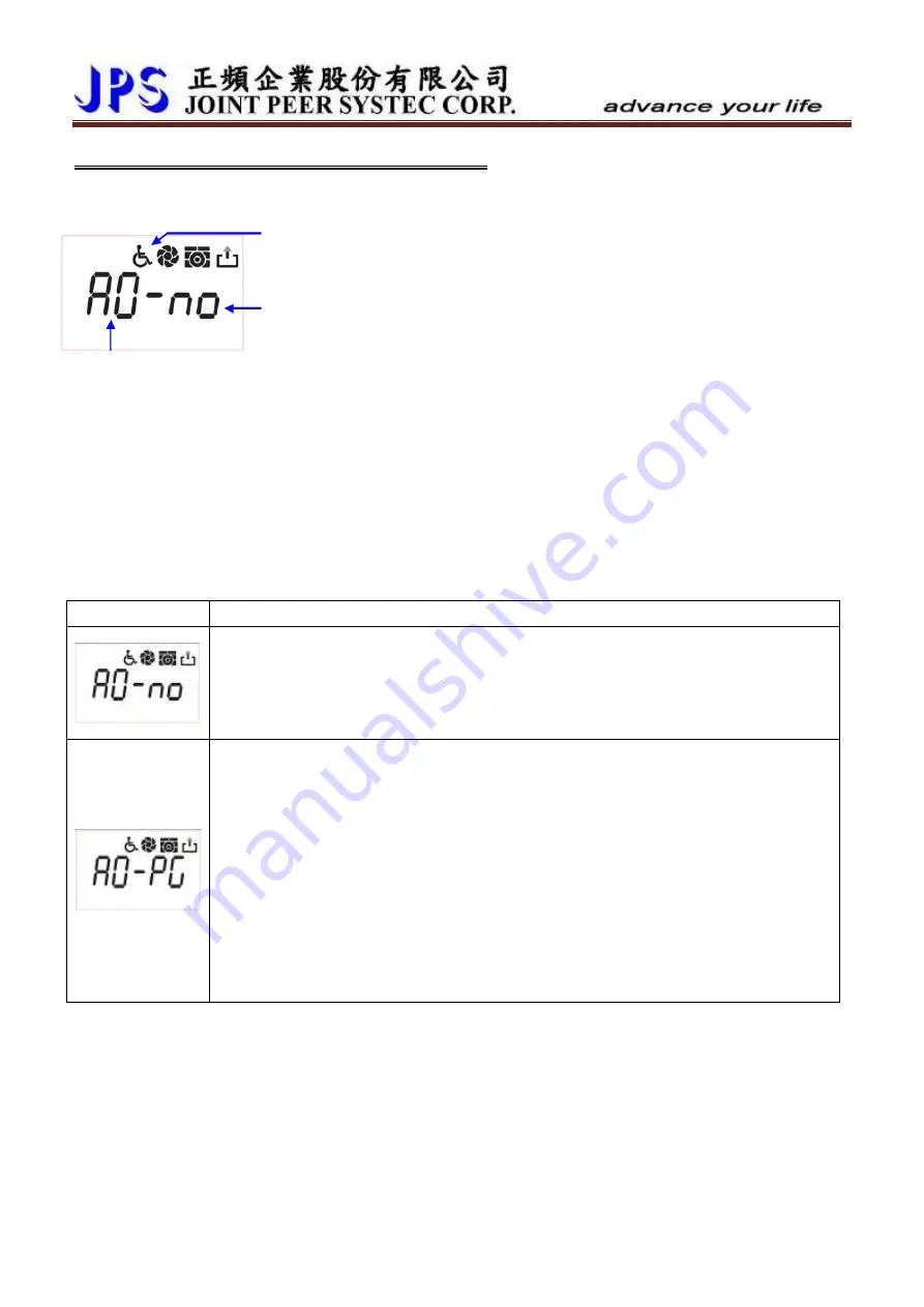
When alarm happened, the LCD display will show message as the
figure showed in the left side. If used panel is COLOR type, the display
back light will turn to red.
www.jps.com.tw
90
The items of the alarm message are Alarm Record and Alarm Message.
The current alarm record is A0, and user can press the up or down keys
to check the earlier records A1, A2, A3.
Every time the drive turned on, the alarm records will be shift to earlier
position, and the A0 will be clear to record the current status.
Alarm
Icon
Alarm Record
Alarm
Message
The Alarm Message description will be explained in next paragraph.
15.2 Maintenance of Alarm Message
When the panel enter the alarm mode, it means that there is important message to show on the LCD display.
The user should treat this condition by following the setps introduced below with serious maner. If still cannot
fix the problem after these methods mentioned in here, please contact with product agency or maintain
department of manufacturer. The basicaly maintenance steps are described below:
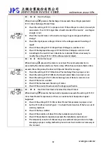
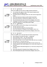
Alarm message
Description and maintenance
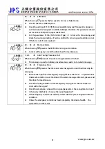
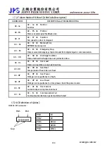
A0 – no
Î
No Alarm
When showing
no
presents there is no alarm.
z
If the driver is in normal condition, the display will show like this way when enter
alarm mode.
A0 – PG
Î
PG feed back Alarm
When showing
PG
presents the encoder feed back signal error.
z
Check the connection of feed back cable. Is there any broken or defect?
z
If the feed back cable is long, make sure there is no serious interference to the
cable.
z
Check the setting of Pr.193 (Magnetic Sensor Check Time) is proper or not.
z
Because the reason of this problem may includes magnetic sensor, therefore,
before sending the driver for maintenance, it is better to replace the driver with
another good condition one to make sure the problem is caused by driver
individually.

