www.jps.com.tw
33
10. IRIS-IMSV Parameter Description
10.1 Driver Specification Group
z
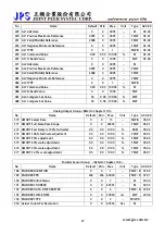
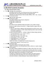
Pr.071
Î
Unit Address (for communication)
This parameter can be set from 1 to 63. If there are above 2 driver connected to the
communication line, the unit address should be set for individual number.
【NOTICE】The communication port format should be 19200bps、8bits、1stop、no parity.
z
Pr.097
Î
System software version
Indicate the CPU software version.
z
Pr.130
Î
Input AC power voltage
This parameter defines the input AC power voltage level:
For 220V driver, it should set 220;
For 380V driver, it should set 380.
【NOTE】
This parameter has been defined well before leaving factory. User should not change it.
If necessary to adjust it, please measure the R, S, T voltage and get the average to write into
this parameter.
※
If the R, S, T input voltage is different form the designed level exceed 10%, please contact
with the agency or producer to confirm. Rashly change this parameter may cause damage
to this driver or public danger.
The driver will follow this parameter’s setting to calculate the followed voltage check level:
※
Over Potential trip level = 1.414 * Pr.130 * 130 %。
※
OP recover level = 1.414 * Pr.130 * 120%。
※
Under Potential trip level = 1.414 * Pr.130 * 70%。
※
UP recover level = 1.414 * Pr.130 * 80%。
※
CONTACTOR ON level = 1.414*Pr.130*69%。
※
CONTACTOR OFF = 1.414* Pr.130*65%。
【NOTE】The Contactor is inside the driver to short the charging resistor.
※
Brake Discharge start level = 1.414*Pr.130*117%。
z
Pr.209
Î
Rated Output Current
This parameter defines the rated output current of driver.
【NOTE】This parameter is set as the specification of driver, and there is no need to change it.
z
Pr.239
Î
Carrier Frequency
This parameter defines the PWM carrier frequency. The range can be set from 2 KHz~16 KHz.
If setting higher carrier frequency, the output waveform will be less distortion for sinusoidal,
and the human ear will hear less noise, but the electronically interference to the environment
will be larger, and generate more switching loss on power module.
If setting lower carrier frequency, the output waveform there will be more distortion for
sinusoidal, and the human ear will hear more noise, but the electronically interference
environment will be less, and the switching loss on power module will be less too.

