FAA Approved Installation Manual for the
Report No 908
EDM-900 and EDM-930
Page 25 of 55 Rev I
Primary Engine Data Management System
Date 1-18-2013
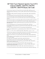
3. Tap
USER
when you see ‘
Do you want to restore user table?
’
(Note: tapping FACTORY
causes the fuel table stored on the Key Card to over-write any previous user entries in the fuel table. Use
FACTORY if you want to start from the original factory default).
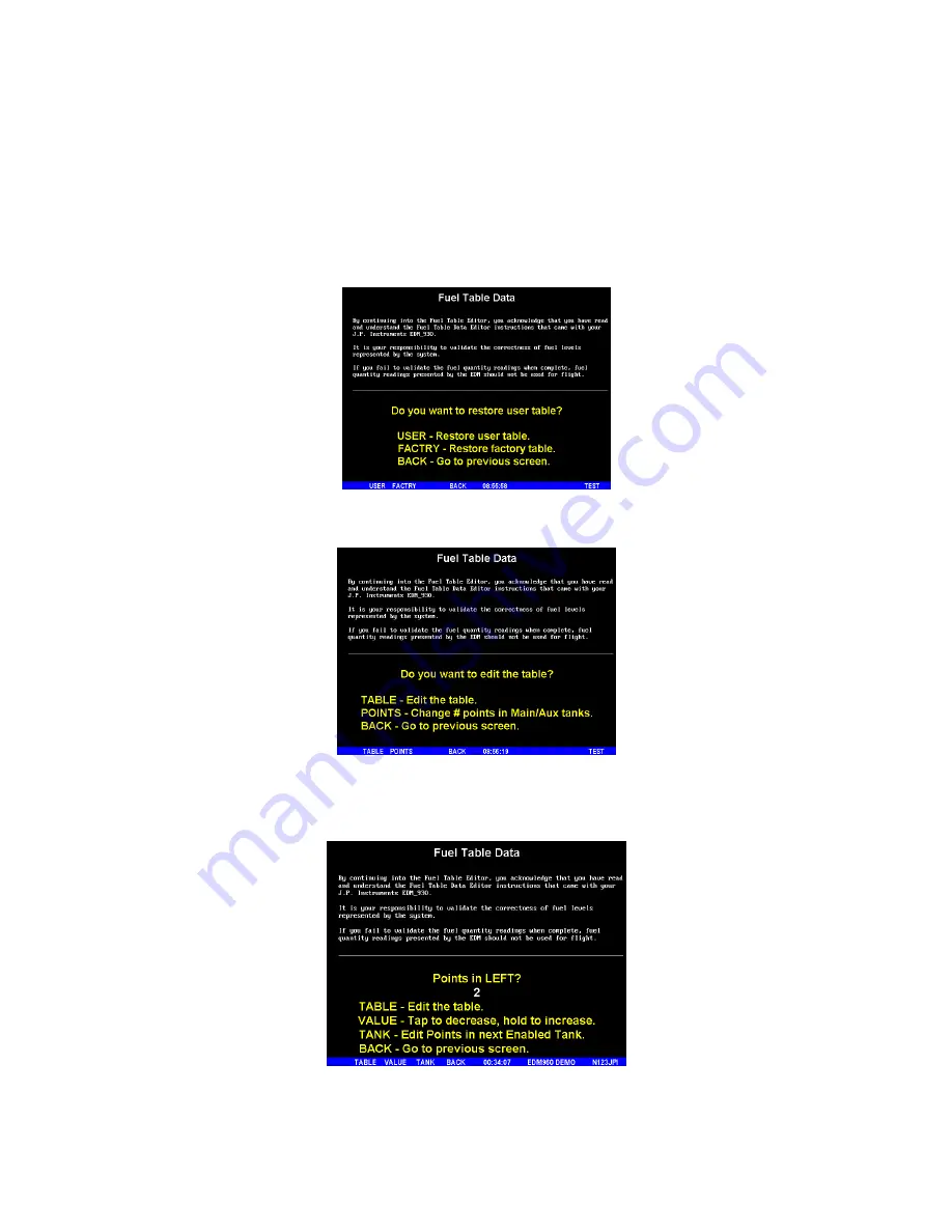
4.
Tap
POINTS
when you see ‘
Do you want to edit the table?
’.
5.
You see ‘
Points in LEFT
’, the current calibration points for the LEFT tank.
6. Tap/hold
VALUE
to change to the desired number of calibration points for this tank (2 to 5). Each
Tank can have a different set of calibration points. So 5 points for Main and 2 points for Aux.