background image


86 

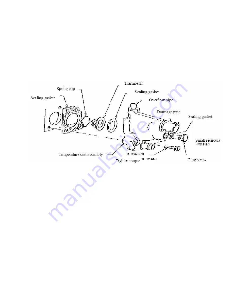
——Loosen three M6

×

40 bolts and remove them   

——Remove thermostat seat with thermostat assembly   

——Pry out spring clip by chisel or screwdriver   

——Take out the thermostat   

——Take out sealing gasket 

  ——Remove sealing gasket of thermostat seat   

Measure the opening temperature of thermostat in hot water.   


                                                                          Fig.125 

——Clip the thermostat seat, and put the rubber seal ring into the thermostat hole.   

——Install the thermostat (with spring outward)   

——Install spring clip, ensure that the clip is clipped in the thermostat seat groove.   

——Install the sealing gasket of the new thermostat seat on the thermostat assembly with a bolt.   

——Install the thermostat together with thermostat assembly into the rear end hole of cylinder head. Finger 

screw in 3 bolts and tighten to 9-12Nm.   

——Tighten the hex head plug with the sealing gasket on. Tightening torque is 38-42Nm.   

——For the engine equipped with electrical heater, install air intake preheating switch. Tightening torque 

is 38-42Nm.   

3. Removal and assembly of the water temperature sensor. Removal:   

——Remove the water temperature sensor (at the exhaust side, under the rear lug).   

Assembly: ——Before installation, apply the lotite 

Summary of Contents for JNSZ1600QL

Page 1: ...IMPORTANT SAFETYINFORMATION MINIMUM RECOMMENDED OPERATOR AG FOR OFF ROAD USE ONLY This vehicle is designed and manufactured for off road use only USA only It does not confirm to federal motor vehicle...

Page 2: ...600QL during the 90 days warranty period please contact your nearest authorized dealer for repairs What is not covered under this warranty This warranty does not cover any sold vehicle that has been s...

Page 3: ...READY TO DRIVE 8 6 IS YOUR VEHICLE READY TO DRIVE 10 7 SAFE DRIVING PRECAUTIONS 12 8 SPECIFICATIONS 13 9 OPERATIONS 14 10 SERVICE INSTRUCTIONS 20 11 REPAIR 26 12 ABOUT ENGINE 27 13 PERIODICAL CHECK A...

Page 4: ...sure to follow the recommended maintenance schedule and service your kart accordingly Preventative maintenance is extremely important to the longevity of your ATV JOYNER believes in conservation and p...

Page 5: ...ing a ATV You must use your own good judgment You will find important safety information in a variety of forms including Safety Labels On the ATV Safety Messages Preceded by a safety alert symbol and...

Page 6: ...TV take time to become familiar with how this ATV works and handles Practice in a safe area until you build your skills and get accustomed to this ATV s size and weight Because many accidents involve...

Page 7: ...V Failure to adhere to this warning will cause physical harm to your body Skidding or Sliding The terrain surface can be a major factor affecting turns Skidding a turn is more likely to occur on slipp...

Page 8: ...information and recommendations to help you drive your ATV safely please take a few moments to read these pages The labels are considered permanent parts of the ATV If a label comes off or becomes ha...

Page 9: ...cle helmet eye protection boots gloves long pants and long sleeved shirt or jacket whenever you drive Although complete protection is not possible wearing proper gear can reduce the chance of injury w...

Page 10: ...th your hands to the ground when the ATV turning over could lead to serious injury or death Never support with your hands to ground when the ATV will turn over Age Recommendation It is strongly recomm...

Page 11: ...ap is securely fastened Check for leaks Tires Use a gauge to check the air pressure Adjust if needed Also look for signs of damages or excessive wear Nuts Bolts Check the wheels to see that the axle n...

Page 12: ...and regulations Obtain permission to drive on private property Avoid posted areas and obey no trespassing signs You should never drive your ATV on public streets roads or highways even if they are no...

Page 13: ...ATV overturning or going out of control Go slowly and be extra careful when operating on unfamiliar terrain Always be alert to changing terrain conditions when operating the ATV Never drive past the...

Page 14: ...k Plug K7RTC Torque Of Spark Plug 17 0 30 0Nm Fuel type RQ90 unleaded Lubricate oil SAE 10W 40 CAPACITIES Maximum load 400kg Fuel tank 58 0L Engine oil 3860ml Coolant 6000ml Starting 5s Climbing 20 25...

Page 15: ...pushed all the way forward the assembly is working smoothly and returns to idle when released Do not operate if pedal or engine throttle linkage fail to return to idle If unable to correct the problem...

Page 16: ...Press the throttle slightly and turn the key clockwise to the on position release the key and the throttle when the engine starts Each time prior to starting the engine check the throttle assembly to...

Page 17: ...il Level Check for transmission Oil Level Check for leaks add oil if required 2 Check the coolant Check for leaks add the coolant if required 3 Check for Fuel Level Add fuel as necessary and do not ov...

Page 18: ...t The seat must always be securely fastened in the position which best allows the operator control of the foot pedals steering wheel and the remote stop key Fig 4 a Pull seat adjustment handle upward...

Page 19: ...then push the parking lever to the bottom b Adjust the parking cable if necessary Park brake OFF Fig 5 Park brake On Fig 6 F Gear Shift Adjustment 1 Loosen the bolts 2 Press down the clutch pedal full...

Page 20: ...st 1000 km 1st Gear 25km h 2nd Gear 45km h 3rd Gear 70 km h Max speed in each gear 4th Gear 100km h H Starting And Operating Instructions a Before starting the engine be sure that the driver is seated...

Page 21: ...if the filter cover and the air filter is dusty please clear the filter cover and replace with a new air filter B Engine Lubrication Engine oil replacement You must change the oil in the crankcase af...

Page 22: ...the engine oil out fully see Fig 9 c Tighten the engine oil outlet plug d Remove the oil filler cap see Fig 10 fill oil SAE 10W 30 50 about 3 86 liters to the engine e Pull out the engine oil dip sti...

Page 23: ...nge the oil in the transmission after the first 5 hours of operating of your new engine and after 10 hours of use thereafter That will insure proper lubrication of internal parts and prevent costly re...

Page 24: ...Remove the plug see Fig 13 fill oil API 80 75 W 90 GL 3 Gear Oil about 2 0 liters Check transmission oil If the color of transmission oil changes you need to replace oil Replace transmission oil as ab...

Page 25: ...re injury Never open the radiator cap while the engine is hot New and used coolant can be hazardous Children and pets may be harmed by new or used coolant Continuous or brief contact with coolant may...

Page 26: ...t to be operated for periods in excess of 30 days or at the end of each driving season prepare for storage as follows a Drain fuel tank by allowing engine to run out of fuel or use a fuel stabilizer b...

Page 27: ...of the wheels The proper toe in dimension A should be 0 63 inches greater than dimension B 3 To adjust the alignments loose the lock nuts on both sides of Front Tie Rods To make Dimension B smaller t...

Page 28: ...ctrolyte of accumulator should be sufficient Don t operate it at high speed at once after starting the engine You should preheat it step by step You d better drive it on cement pavement or asphaltum p...

Page 29: ...gnition I 9 Air cleaner C I 10 Throttle cable I A L I R A 11 Fuel tank cover Breathe hose and joint I I R 12 Idle I 13 Breathe hose I 14 Fuel hose and joints I I I R Control system 15 Wire and plugs I...

Page 30: ...mshaft oil seal removal and installation 47 8 Valve mechanism and cylinder head removal check and installation 48 9 Piston and connecting rod assembly removal and installation 57 10 Flywheel assembly...

Page 31: ...control fuel injection system and multipoint electric control fuel injection system of the above engines are developed though the joint effort with Italy M M Corp With advanced product performance re...

Page 32: ...31 ENGINE CONFIGURATION VIEW AND SECTIONAL VIEW Fig 22...

Page 33: ...32 Fig 23 Fig 24 Fig 25 1 Temperature regulator seat assembly 11 Camshaft thrust plate 2 Temperature regulator seat 12 Camshaft timing gear...

Page 34: ...meters CAC480M Type Line 4 cyl four strokes water cooling Cylinder bore diameter mm 79 94 Stroke mm 79 52 Total displacement L 1 596 Compression ratio 9 75 1 Nominal power RPM 62 5500 kW r min Total p...

Page 35: ...5 Application parameters Lubricant With temperature at 10 or more SAE10W 30 50 grade SF Gasoline 93 SH0041 Common unleaded Gasoline Engine oil pressure Idling 100kPa min 2000r min 80 280kPa min Engine...

Page 36: ...n Steel strip combination oil ring With scape blade excircle chroming 5 Piston pin Low carbon steel Surface carbonizing and quenching Semi floating structure Interference fit with small end of connect...

Page 37: ...nitrile rubber 19 Intake manifold Made from Aluminum alloy With mixture warm upped by water jacket Electric heated intake manifold is optional 20 Exhaust manifold Made from ductalloy or black cast iro...

Page 38: ...on contact distributor Driven by the rear end of camshaft Type is FDW451 JFD459 Only applied for carburetor engine 32 Ignition controller Type are ZJ5701 HG KH 3A Only applied for carburetor engine 33...

Page 39: ...tube for cracking Check PCV valve Check spark plugs Per16000km Check accessories drive belt Check timing belt and tension pulley Check radiator and hoses for leaking Per30000km Replace fuel filter Pe...

Page 40: ...r filter core and clean case Check accessory driving belts Check radiator and hoses for leaking Replace spark plugs Replace timing belt Replace fuel filter Check high tension wires Check lambda sensor...

Page 41: ...shaft pulley aligns with the TDC mark 0 on timing gear cover Note Before rotation spark plugs may be removed to reduce effort Fig 27 Check whether the TDC mark on the camshaft gear aligns with the mar...

Page 42: ...e TDC mark on the front end of cylinder head if not aligned rotate crankshaft one turn aligning the TDC mark on camshaft gear with the TDC mark on the front end of cylinder head 2 Upper and lower timi...

Page 43: ...on crankshaft finger screw in 2 bolts and tighten to 9 0 11Nm Clean upper timing gear cover Mount new seal gasket with shot nail or glue on lower timing gear cover Install upper timing gear cover seal...

Page 44: ...Install pulley on crankshaft journal aligning keyway with semicircular key Slip cushion block onto bolts and finger screw in Block flywheel ring gear with screwdriver preventing crankshaft from turnin...

Page 45: ...acting surface Push the wedge of valve cover seal gasket into appropriate valve cover groove integrating valve cover with seal gasket Install valve cover and seal gasket assembly on cylinder head Inst...

Page 46: ...row indicated in diagram push tension pulley aside with a large screwdriver To release belt tension tighten 2 tension pulley mounting bolts with tension pulley in this position To reuse belt mark the...

Page 47: ...2 turns until no 1 cylinder reaches its TDC of compression Grab the midway of the right side belt between crankshaft gear and camshaft gear with thumb and forefinger If belt tension is as specified b...

Page 48: ...mshaft gear Camshaft gears are not permitted to be exchanged between 480 engine during replacement the mark on the original gear should be referred Fig 40 Installation Check gear tooth for wear pittin...

Page 49: ...ey Installation Check gear tooth for wear pitting or scratch Install semicircular key protrusion should be 1 392 1 739mm Install shim with curved face side forward Install crankshaft gear with boss si...

Page 50: ...lean the oil seal hole in cylinder head apply clean engine oil on oil seal edge and camshaft oil seal journal install oil seal on oil seal journal carefully push oil seal in perpendicularly into place...

Page 51: ...50 1 Valve mechanism for 480 engine Fig 44 2 Cylinder cover bolts removal and cylinder head assembly installation Fig 45 Fig 46...

Page 52: ...ld not be deposits in tapped hole or fluid pressure resulting from bolts screwing may possibly results in cylinder block cracking Rotate crankshaft until no 1 cylinder piston is 20mm or so under the d...

Page 53: ...ate 90 During rotating torque angle torque wrench or line plotting methods may be applied 3 Rocker arm mechanism and hydraulic lifting rod removal and installation Rocker arm mechanism removal Loosen...

Page 54: ...53 Fig 52 Fig 53...

Page 55: ...r arm rocker arm support then finger screw in new nut tighten to 25 29Nm Note Before installing each rocker arm and tightening nut appropriate hydraulic lifting rod should be at thelowest position Hyd...

Page 56: ...tallation removal Measure camshaft end play clearance should be 0 049 0 129mm Loosen thrust washer bolt remove thrust washer bolt as shown in diagram Remove thrust washer Pull camshaft assembly out fr...

Page 57: ...t journal diameter Cylinder head bearing hole diameter 1 45 12 45 14 45 163 45 188 2 45 37 45 39 45 413 45 438 3 45 62 45 64 45 663 45 688 4 45 87 45 89 45 913 45 938 5 46 12 46 14 45 163 45 188 Insta...

Page 58: ...ut an appropriate pipe on spring seat so the valve locking piece will not be impacted Put a wooden block on valve head with cylinder head combustion chamber facing workbench and then strike pipe end w...

Page 59: ...iameter Valve guide hole diameter Clearance Valve stem diameter Valve guide hole diameter Clearance Standard 8 043 0 0 018 8 063 8 094 0 02 0 069 8 017 0 0 018 8 063 8 094 Oversize0 4 8 443 0 0 018 8...

Page 60: ...der head valve or valve guide Lubricate the valve stem and guide with clean engine oil Install the valve Notice that the intake and exhaust valve for 480 are not interchangeable Refer to the previous...

Page 61: ...of intake valve seat and cylinder head valve seat hole Fig 71 Diameter of intake valve seat Diameter of the cylinder head valve seat hole Press fit clearance Standard 43 877 0 01 44 763 0 025 480 0 0...

Page 62: ...fore removal Remove the connecting rod bolts and remove the rod cap Take the connecting rod bushing out and stick on cylinder marks and labels on the upper or lower halves Push the connecting rod and...

Page 63: ...t should be taken at the position 10mm to the bottom skirt For 480E piston measurement should be taken at the position 19mm to the bottom skirt Unit mm 478 dia of piston skirt mm 488 dia of piston ski...

Page 64: ...63 Oversize 0 5 77 71 77 735 80 43 80 455 80 465 80 475...

Page 65: ...cotter intermission of piston ring First compression ring 0 30 0 50mm Second compression ring 0 30 0 50mm Steel combination oil ring 0 40 1 40mm Measure the piston ring end play in the piston groove U...

Page 66: ...iston head means the front arrow The outer end of piston pin means the front lug which should has a same direction with F near the large end of the connecting rod with 480 mark on some blanks and the...

Page 67: ...ssembly by hammer into the cylinder bore Apply engine oil on the connecting rod bushing Mount connecting rod cap Retain connecting rod body and cap with two elastic retaining pins Tighten connecting r...

Page 68: ...he real oil seal Removal Remove 4 bolts as arrow indicates Take out carrier assembly of the real oil seal Remove carrier sealing gasket of the real oil seal Use chisel or screwdriver to pry the real o...

Page 69: ...ator to and then use post to push the crankshaft toward such as possible Check dial indicator The reading is end play The end play of the crankshaft should be 0 092 0 303mm If dial indicator is not av...

Page 70: ...ed in the cover of plastic clearance gauge Check the bearing clearance from the third main bearing and extending to the two sides The clearance of main bearing is 0 011 0 058m m Check clearance of con...

Page 71: ...e diameter of main bearing bore of cylinder body The thickness of main bearing half shell Standard 57 98 58 00 62 2935 0 0065 2 131 2 138 Oversize 0 4 57 98 58 00 62 6935 0 0065 2 331 2 338 Undersize...

Page 72: ...4 0 03 28 825 28 875 2 326 0 025 Oversize 0 38 24 0 03 29 205 29 255 2 516 0 025 Installation Before installation use the second screw tap taps the threaded hole in cylinder body especially the thread...

Page 73: ...ress fit between rabbet and cylinder body The press fit clearance is 0 025 0 145mm After installation the surface of the first and the fifth main bearing caps should be even or lower than the front an...

Page 74: ...gh oil passage in the crankshaft There is a small oil port in the connecting rod bearing bore near the exhaust side in the connecting rod body The oil sprays out from this small oil port to lubricate...

Page 75: ...sealant on the joint place between flange surface of oil pan of cylinder body and oil pump case and carrier of real oil seal Put the new rubber seal gasket on the cylinder body and have the two sides...

Page 76: ...75 Replace the sealing gasket of drain plug Screw in the drain plug by hand and tighten to 21 25Nm...

Page 77: ...ng washers Installation Install a new sealing gasket of oil collector on the flange face of oil pump and then install oil collector assembly Screw two bolts with gasket by hand Fig 101 Fig 102 Screw t...

Page 78: ...l flange surface bolts Remove the bolts as the figure indicates Remove oil pump with oil seal assembly Pry out the front oil seal of crankshaft by screwdriver or chisel Note Don t damage the front oil...

Page 79: ...tor of oil pump The radial clearance between inner rotor and outer rotor of oil pump should be 0 05 0 18mm Check the end play of rotor The end play of rotor should be 0 014 0 100mm Remove horizontal h...

Page 80: ...nto the oil pump bore Screw 3 8 plug screw into the oil pump house Keep it in place Tightening torque is 20 25Nm Stick the new oil pump sealing gasket on the front end of cylinder block Install the oi...

Page 81: ...r Removal Remove the oil filter Rotate oil filter counterclockwise during removal Remove the oil pressure sensor Installation Apply engine oil on the sealing gasket of oil filter and screw into the co...

Page 82: ...temperature reaches the point for thermostat to open the coolant for cooling cylinder block going through the opened thermostat combusting chamber and behind the valve seat will go into the right wate...

Page 83: ...ting temperature Grade 95 thermostat Grade 102 3 opening temperature 85 89 cut off temperature Grade 84 wide opening temperature 89 102 Grade 91 resistance temperature 70 159 21 3 90 86 7 11 110 52 3...

Page 84: ...oming out from the water pump inlet is clean Add coolant 1 Before adding coolant check if the drain plug of radiator is closed and if the pipeline is connected and tight 2 Remove the pressure cap and...

Page 85: ...er pump case water pump impeller water pump gear water pump bearing water pump seal ceramics black lead Removal Loosen and remove four bolts from the front end of cylinder block Remove water pump asse...

Page 86: ...ining bolt by hand then tighten to 7 0 10 0Nm Note The water pump assembly may not be serviced When water seal or bearing is damaged the water pump assembly should be replaced 3 The removal and instal...

Page 87: ...is clipped in the thermostat seat groove Install the sealing gasket of the new thermostat seat on the thermostat assembly with a bolt Install the thermostat together with thermostat assembly into the...

Page 88: ...Fig 126 intake and exhaust system arrangement of carburetor engine The air filter is equipped with an intake air temperature controller When the temperature is low the hot air intake valve controlled...

Page 89: ...ve controlled by the temperature controller will open and the hot air flowing by the exhaust manifold will be directed into the air filter from the intake preheating hose to supply more hot air and fa...

Page 90: ...preheating switch is installed in the M22 bolt hole in the thermostat seat with the hole plugged by plug screw for carburetor engine The intake preheating switch s operation parameters Switching off t...

Page 91: ...M8 nuts Assembly Apply lotite sealant 201 on the cylinder head bolt threads and screw six studs into the cylinder head Assemble the new sealing gasket onto the studs Install the intake manifold assemb...

Page 92: ...14 19Nm install the rear lug and tighten allen screw with hands tightening torque is 50 60Nm 5 For oxygen sensor and 3 way catalyst Converter See CAC480M Engine s single port injection system 16 Posi...

Page 93: ...fle assembly PCV pipe cylinder block PCV hose PCV valve 3 way connector valve chamber cover connecting hose and ventilation hose 2 2 PCV valve s function Under the low speed condition the vacuum of in...

Page 94: ...of the carburetor engine Fig 134 Fig 135 1 1 Description of the fuel supply system The fuel in the tank flows into oil filter pumped by the fuel pump and goes into carburetor after being filtered thro...

Page 95: ...e oil into the rod s hole of the cylinder head and install the push rod into the hole The gap between push rod and hole is 0 035 0 055mm Screw in the studs into the threaded hole and tighten with the...

Page 96: ...ld Screw the studs into intake manifold and tighten them with nuts Tightening torque is 8 10Nm Adjustment The carburetor adjustment mentioned in this introduction only specifies the idle speed adjustm...

Page 97: ...r from the fuel tank goes into the charcoal canister by fuel vapor pipe and is sucked into air intake pipe though the fuel vapor recirculation solenoid valve which is controlled by ECU For more detail...

Page 98: ...not beyond 40V During servicing the alternator apply enough No 2 lithium base grease into the alternator sealing bearing for the operation period before the next service The electronic regulator needs...

Page 99: ...ndependent assembly 2 Starter Rated output 0 95kW Speed range 1000 1800r min Voltage 12V Type QDY1258 SD6RA78 The flywheel gear ring for vehicle and the one for independent engine assembly is differen...

Page 100: ...brush spring is pressed on the brush correctly Pay more attention to keep the wire bayonet clip clean Make sure there s no oil fouling and water Or the voltage drop is too high and the engine doesn t...

Page 101: ...er TDC mark on the distributor flange Install the distributor inserting the lug into the camshaft groove Rotate distributor to align the mark on distributor flange with the mark on cylinder head Tight...

Page 102: ...lywheel gear ring or starter 7 No engine ground wire or ground wire is disconnected Connect or replace the ground wire 2 Engine runs but no spark exists during starting Cause Correction 1 No fuel in f...

Page 103: ...rature is high Cause Correction 1 Air filter is dirty or blocked Clean air filter core or replace case 2 Low cylinder compression pressure Sent to service spot for check and service 3 Hydraulic valve...

Page 104: ...ct Check fast idling spring for fallout readjustment 7 Low or unstable Cylinder compression pressure Check and service 8 Timing belt tightening incorrectly Adjust timing belt tension 9 Idle mixture to...

Page 105: ...rvice 10 Engine accelerates hesitate Cause Correction 1 Intake manifold or connecting hose vacuum leaking Service and check 2 Fuel filter clogged Replace fuel filter 3 Fuel pump damaged Or low fuel ou...

Page 106: ...ne ignited too late Check or adjust distributor 2 Incorrect Timing belt assembling or Adjust teeth belt tension and tension pulley inadequate belt tension 3 Carburetor fuel level too low or Check and...

Page 107: ...utor b Incorrect fuel grade Use fuel of correct grade c Intake manifold or connecting hose vacuum leakage Check and service d Too much carbon deposits in Spark plug or combus tion chamber carbon sever...

Page 108: ...abnormal 5 Expansion tank pressure cap damaged Replace 6 Water pump leaks or damaged Service or replace 7 Ignition timing too late Adjust ignition timing 8 Air exists in cooling system Bleeding the a...

Page 109: ...108 7 cylinder compression pressure decreases check engine 8 Incorrect ignition timing adjust ignition timing 9 Too low tire pressure inflate the tire...

Page 110: ...hrottle valve body 3 Two BAE 800 AK Ignition coil The whole system includes fuel pump fuel filter RPM sensor absolute pressure sensor sensor and so on Fig 159 1 Fuel tank 2 Fuel pump 3 Fuel filter 4 C...

Page 111: ...ting device to integrate idle speed spray ignition s control Moreover HCMOS microprocessor with wonderful static prevention and high speed calculation ability and low power consumption may fulfill the...

Page 112: ...pped and ignition switch is on ECU may perform active diagnostic function which may operate ECU microprocessor to check whether the following accessories are running well or not fuel pump fuel injecto...

Page 113: ...hrottle valve Throttle valve features small accessories compact structure and a bran new inner geometry structure to better the fuel atomization from fuel injector and get the most proper mixture for...

Page 114: ...0 9 1bar and redundant fuel will recirculate flowing into fuel tank Fuel will clean and cool injector during recirculation Working procedure of Fuel pressure regulator Spring 2 applies pressure on the...

Page 115: ...g corrosive material is applied figure 164 shows fuel injector structure and some technical parameters Technical parameters winding resistance R 1 8 10 20 power supply voltage V 6 16V spraying shape a...

Page 116: ...ngine warming up As accelerator pedal is released fuel will be cut off ti 0mS Running condition and readjusting condition may be changed according to water intake air temperature or A C condition inta...

Page 117: ...ction when working condition comes back ECU supplies 5V voltage to the variable resistance terminal of throttle valve potentiometer And potentiometer output voltage varies with throttle valve position...

Page 118: ...m idle air intake is set by valve returning position i e about 200 steps 8mm travel The operation steps are the function of engine conditions preheating cycle electrical load A C working condition eng...

Page 119: ...61 from the sensor When engine is warmed enough for fan to reach the operation range the enrichment is zero 4 2 speed top dead center and s s s synchro pickup CVM01 see figure 170 Fig 170 Sensor is mo...

Page 120: ...ched see figure 171 Fig 171 Speed TDC sensor Check if the sensor is located in the twentieth tooth after the breach in the flywheel signal panel 1 Speed TDC sensor crankshaft position sensor 2 Pulley...

Page 121: ...mospheric pressure mmHg After the ignition switch is switched on the actual atmospheric pressure may be obtained by this method When engine is running the vacuum will produce a mechanical effect on th...

Page 122: ...figure 175 When ECU microprocessor identifies the signals of two tooth missed signals it will begin to count tooth Cylinder 1 or cylinder 4 TDC comes after 20 teeth are counted Cylinder 2 or cylinder...

Page 123: ...l engine the combustion is produced by the reaction of hydrogen and oxygen and then emits heat Fuel is composed of hydrocarbons It includes carbon atom and hydrogen atom which are combined together by...

Page 124: ...h a heating unit 4 to reach the operation temperature as soon as possible When the current flows over the heating unit it shortens the time for ceramic becoming the conductor of iron and may have the...

Page 125: ...verter capability for the chemical reaction should not occur within 80 thousand kilometers or five years Besides lead the unburned fuel in the converter is another factor for the catalytic converter f...

Page 126: ...it exceeds a specified pressure the multi function valve 4 will permit the fuel vapor to reach the charcoal canister 6 and be absorbed by the activated carbon granule The operation when engine is run...

Page 127: ...the neighboring magnet attraction Under the specified accelerating load the steel ball is released from the magnetism stillness and begins to move up the cone seat with the travel of the movement dep...

Page 128: ...l cylinder 1 4 9 Dual relays A ECU B fuel pump 10 sensor 11 Fuel pump 4 Fuel injector 12 Fuel vapor recirculation solenoid 5 2 ignition coil cylinder 2 3 13 ECU 6 Ignition switch 14 Main ground wire o...

Page 129: ...128 Fig 181...

Page 130: ...unter 27 Throttle valve position sensor 8 Ignition coil 1 cylinder 1 4 28 Main ground wire of engine 9 Ignition coil 2 cylinder 2 3 29 Absolute pressure sensor 10 Fuel vapor recirculation solenoid 30...

Page 131: ...nection line 23 Fuel pump relay speed counter signal 11 Tacho sensor negative input 24 A C relay signal see note 12 sensor negative input 25 Without connection line 13 Water temperature sensor negativ...

Page 132: ...tem service Fig 183 A C input and signal if euipped Note 1 All connector are viewed from the intake side of the cable 2 Cable color and number indicates the 35 pin ECU connector connection of injectio...

Page 133: ...ter temperature sensor 18 Fuel vapor recirculation solenoid 10 Absolute pressure sensor 19 sensor connector 11 Intake air temperature sensor Self diagnosis system The information is stored permanently...

Page 134: ...r the corresponding signal channel fails the above program is also applied When a failure is detected and the corresponding substitute value is applied the warning light on the instrument panel will t...

Page 135: ...e sensor Remove sensor from the case During reassembling grease should be applied on threads Antiseize boron nitrogen grease is recommended Tightening torque 0 5 0 6Nm At ambient temperature The resis...

Page 136: ...sensor or intake air temperature sensor The temperature indicated should be in the vicinity of the ambient temperature Idle intermittent wave 1 Throttle valve body 30MM4 1 check the throttle valve cab...

Page 137: ...dy check fuel filter and fuel pipes TRANSMISSION MAINTENANCE AND SERVICE Page 1 Outline Drawing of AQ015D Transmission 129 2 Specifications 130 3 Structural Type and Applicability 131 4 Service and Op...

Page 138: ...137 Outline Drawing of 5T15 Transmission...

Page 139: ...138 Fig 189 Specifications...

Page 140: ...Reverse Speed 38 12 3 167 Rated Power 65KW Rated Torque 133Nm Rated Speed 6300r min Lubricating Oil Capacity 2 0L Lubricating Oil Type API 80 75 W 90 GL 3 Gear Oil Input Shaft Spline 24 Teeth Involut...

Page 141: ...oth driving low noise and long service life etc The transmission is mainly matched with CAC480 series of engines single point injection and multi point injection Service and Operation 1 When shifting...

Page 142: ...141 Fig 191 1 Clutch Housing 2 Input Shaft 3 Output Shaft 4 1st Speed 5 Reverse Speed 6 2nd Speed 7 3rd Speed 8 4th Speed 9 Transmission Case 10 Rear Case 11 Main reducing gear...

Page 143: ...screwed off The oil is drained away Fig 192 The release lever of clutch is drawn out Fig 193 The bolts connecting the rear case and the transmission are screwed off The rear case assembly is removed A...

Page 144: ...ift shaft is screwed off with special tool The spreader spring and shift shaft assembly are taken out Fig 196 The locking screw of reverse speed shaft is removed Fig 197 5th speed driven gear clamping...

Page 145: ...and its up and down spring are taken out And then 5th speed fork guiding plate and 5th speed fork sleeve component the reverse speed fork guiding plate 3rd and 4th speed fork and 1st and 2nd speed for...

Page 146: ...ar needle bearing and synchronizer ring are removed If necessary the special tool may be used Fig 203 The idler shaft is tapped upward with the reverse speed idler Until the idler and idler shaft are...

Page 147: ...When the differential assembly is installed on the clutch housing the output flange will be not installed temporarily 2 The output assembly is installed And the output shaft mid bearing seat is set T...

Page 148: ...gear are installed When the 3rd speed driven gear is installed the shoulder side is toward the 2nd speed driven gear Fig 210 7 After the 3rd speed driven gear is installed the axial size should be adj...

Page 149: ...212 9 The fork assembly is installed in the right postion 1 1st and 2nd speed fork 2 3rd and 4th speed fork 3 5th speed fork guiding plate and sleeve 4 reverse speed fork guiding plate Fig 213 10 The...

Page 150: ...h 25Nm of force moment The input shaft rear bearing retainer is screwed down with 15Nm force moment Notice The fork shaft is not drawn from 5th speed sleeve Otherwise the fork shaft in the case and th...

Page 151: ...ng force moment is suitable to the oil free bolt and nut Bearing When the needle bearing is installed the thick and big wall side is toward the installation tool When installed the bearings are lubric...

Page 152: ...al Conical roller Bearing Not Adjusted Adjusted Output Shaft Adjusted Not Adjusted Output Shaft Mid bearing Seat Adjusted Not Adjusted Differential Case Not Adjusted Adjusted Output Shaft Mid Bearing...

Page 153: ...is installed to the position that is shown in the figure And then the release shaft the spring and the clamper are installed When the spring in installed its position is show in the figure The new re...

Page 154: ...use the special tool is inserted into the transmission case As the figure shown the bearing is tapped till the bearing is stretched out Fig 221 Installation Fig 222 As the figure shown the special to...

Page 155: ...seat is inward pressed With the aid of the way the spring in the seat is compressed And the position is kept In this condition the clamping ring is removed Installation The process of installation is...

Page 156: ...al tool The bearing is ensured in position Fig 227 Dismantlement and Installation of Input Shaft Oil Seal Dismantlement When the oil seal is removed the transmission assembly is not broken down The oi...

Page 157: ...changed the installation position of relative shaft must be readjusted Adjustment of Output Shaft and Differential Assembly Adjustment of Output Shaft The distance B1 from the big plane of output sha...

Page 158: ...ace of the assembly bearing outer ring to the contact surface of clutch housing is measured The bearing hole depth A2 of output power assembly on the transmission case is also measured To Calculate th...

Page 159: ...eal washer and recoated Bruised joint face and not refaced in time To inspect and reface the joint face Leaking Oil Damaged differential bearing To change the bearing Improper adjusted clutch not thor...

Page 160: ...onizer ring 1 14 015 311 295 AA 4th and 5th speed synchronizer ring 2 15 015 301 189 AA Oil seal assembly output flange 2 16 015 311 113 AA Oil seal assembly output shaft 1 17 015 301 227AA Oil seal a...

Page 161: ...160 WIRING DIAGRAM...

Page 162: ...ut Shaft Assembly 171 4 Output Shaft Assembly 172 5 Rear Cover assembly 174 6 Output assmebly 175 BODY 1 Frame assembly 176 2 Engine bracket and muffler assembly 177 3 Gear shift mechanism 180 4 Steer...

Page 163: ...162...

Page 164: ...163...

Page 165: ...164...

Page 166: ...165...

Page 167: ...166...

Page 168: ...167...

Page 169: ...168...

Page 170: ...169...

Page 171: ...170...

Page 172: ...171...

Page 173: ...172...

Page 174: ...173...

Page 175: ...174...

Page 176: ...175...

Page 177: ...176...

Page 178: ...177...

Page 179: ...178...

Page 180: ...179...

Page 181: ...180...

Page 182: ...181...

Page 183: ...182...

Page 184: ...183...

Page 185: ...184...

Page 186: ...185...

Page 187: ...186...

Page 188: ...187...

Page 189: ...188...

Page 190: ...189...

Page 191: ...190...

Page 192: ...191...

Page 193: ...192...

Page 194: ...193...

Page 195: ...194...

Page 196: ...195...

Page 197: ...196...

Page 198: ...197...

Page 199: ...198...

Page 200: ...199...

Page 201: ...200...

Page 202: ...201...

Page 203: ...202...

Page 204: ...203...

Page 205: ...204...

Page 206: ...205...

Page 207: ...206...

Page 208: ...207...

Page 209: ...208...

Page 210: ...209...

Page 211: ...210...

Page 212: ...211...

Page 213: ...212...

Page 214: ...213...

Page 215: ...214...

Reviews: