Joy-it MOTOPI Manual Download Page 7

www.joy

-

it.net


Pascalstr. 8 47506 Neukirchen

-

Vluyn


6. CONTROLL OF THE ADDITIONAL  CONNECTIONS


After  the  restart,  you  must  install  the  necessary  drivers  and  modules. 

Therefore perform the following commands:


sudo apt

-

get update


sudo pip install spidev


sudo pip install wiringpi


A restart is now required again.


sudo reboot


After the restart, the connections are ready to use. 


Please note that the first pin of the digital connection is connected with 

the GPIO pin 27 and the second pin to the GPIO pin 22.


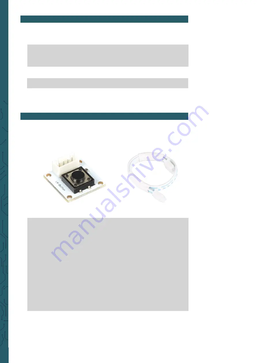
7. CODE EXAMPLE TO USE THE DIGITAL CONNECTIONS


Here, you have a short code example for controlling the digital connec-

tions. For that, we use the 

LK

-

Button1 with a LK

-

Cable

-

20 from our Lin-

kerKit series.


import


RPi.GPIO


as


GPIO


from


time


import

 sleep


#Initialisiere Button auf Digital

-

PIN 22


button = 

22


GPIO.setwarnings(

False

)


GPIO.setmode(GPIO.BCM)


GPIO.setup(button, GPIO.IN, pull_up_down=GPIO.PUD_UP)


while


True

:


if

 GPIO.input(button) == GPIO.HIGH:


#Mache etwas


print

 "Ich tue etwas"


else

:


#Mache etwas anderes


print

 "Ich tue etwas anderes"


Summary of Contents for MOTOPI

Page 1: ...tor control for the Raspberry Pi 1 GENERAL INFORMATION Dear customer Thank you for purchasing our product In the following we will show you which things should be noted during the use Should you encou...

Page 2: ...ase plate is made out of 4 5 mm thick acryl and has mounting holes for all common singleboard computer and microcontollers 3 TECHNICAL DATA SAFETY INSTRUCTIONS The MotoPi board is equipped with 16 cha...

Page 3: ...on The power supply must be adjusted to the power of the connected mo tors If the power supply is insufficiently dimensioned the motors will stutter instead of moving smoothly We recommend the use of...

Page 4: ...image on your SD card Choose therefore like shown in the picture below the image and your SD card After that you can start the writing process with Write If this step is successfull you can put the SD...

Page 5: ...www joy it net Pascalstr 8 47506 Neukirchen Vluyn Enable the function SPI Confirm the next windows all with Yes or rather Ok Afterwards you must enable the function I2C...

Page 6: ...mend using unconditionally and exclusively our own adjusted library This library can be downloaded here Copy the unzipped library completely on your Raspberry Pi and navigate in the terminal into this...

Page 7: ...ital connection is connected with the GPIO pin 27 and the second pin to the GPIO pin 22 7 CODE EXAMPLE TO USE THE DIGITAL CONNECTIONS Here you have a short code example for controlling the digital con...

Page 8: ...e 20 from our LinkerKit series Note that if not all connection are taken the free pins can issue false values import spidev import time import sys spi spidev SpiDev spi open 0 0 spi max_speed_hz 20000...

Page 9: ...else print _______________________________________ n print Channel 0 value readadc 0 volts value 3 3 1024 print 4d 1023 5 3f V value volts print Channel 1 value readadc 1 volts value 3 3 1024 print 4...

Page 10: ...product in normal household quantities 1 Possibility of return at our company location during our opening hours Simac Electronics Handel GmbH Pascalstr 8 D 47506 Neukirchen Vluyn 2 Possibility of ret...

Reviews: