background image


Doc. No.: 84145 Rev. L 

jotron.com


Page 16 of 40 

7


Installation 

Tron SART20 can be mounted several ways near the emergency exit of the 

vessel. Normally, in the wheelhouse at the starboard or port exit (or both 
depending on the requirements) and inside a lifeboat/liferaft.  

7.1


Brackets 

There are two different mounting brackets available. 


Wall bracket 


Lifeboat bracket (with or without a pipe clamp) 

7.1.1


Mounting the wall bracket 

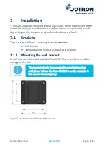
A wall bracket is delivered with the Tron SART20 and should be used for 
storage of the unit. 


The bracket should be mounted in a vertical position 
and placed where the Tron SART20 is easily available in 
the case of an emergency. 


Figure 8 Illustration: Wall bracket dimensions 

Summary of Contents for Tron SART20

Page 1: ...Tron SART20 Radar Transponder User Manual...

Page 2: ...This page is intentionally left blank...

Page 3: ...afety System IEC International Electrotechnical Commission IMO International Maritime Organization ITU International Telecommunication Union LED Light Emitting Diode MED EU Marine Equipment Directive...

Page 4: ...racket 18 7 2 Non bracket mounting options 21 7 2 1 Mounting the lanyard 22 7 2 2 Mounting the Liferaft mounting strap 23 7 2 3 Mounting the telescopic pole 23 7 3 Replacing the battery module 25 7 3...

Page 5: ...Brackets 36 12 3 1 Wall bracket 36 12 3 2 Lifeboat bracket 36 13 Optional accessories 36 14 Spare parts 36 14 1 Counterfeit spare parts 36 15 Recycling and disposal 36 16 Warranty 37 17 Service 37 17...

Page 6: ...wall mount 17 Figure 11 Illustration Lifeboat bracket disassembled 18 Figure 12 Illustration Lifeboat bracket dimensions 19 Figure 13 Illustration Mounting interior exterior wall 20 Figure 14 Illustr...

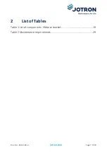
Page 7: ...Doc No 84145 Rev L jotron com Page 7 of 40 2 List of Tables Table 1 List of components lifeboat bracket 19 Table 2 Maintenance requirements 29...

Page 8: ...ined within this manual has been verified and is to Jotron s knowledge correct Jotron reserves the right to make changes to any product s or module s described herein to improve design function or rel...

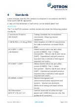
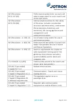
Page 9: ...SOLAS ships IEC 61097 1 1992 withdrawn Global maritime distress and safety system GMDSS Part 1 Radar transponder Marine search and rescue SART Operational and performance requirements methods of testi...

Page 10: ...nce Standards for Survival Craft Radar Transponders for Use in Search and Rescue Operations IMO Resolution A 694 17 General requirements for shipborne radio equipment forming part of the global mariti...

Page 11: ...n SART20 is interrogated by a radar signal it will immediately start to transmit several sweeps covering the complete maritime 3cm radar band The sweeps are used to navigate directly towards the Tron...

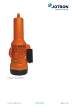
Page 12: ...Doc No 84145 Rev L jotron com Page 12 of 40 Figure 1 Tron SART20...

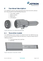
Page 13: ...n parts Transmitter module Battery module Bottom lid LED indicator Figure 2 Illustration Tron SART20 disassembled 6 1 Transmitter module Tron SART20 transmitter module is inserted into the Tron SART20...

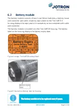
Page 14: ...y label on the Tron SART20 housing displays the expiry date A new battery comes complete with cable and connector The battery module is inserted into the Tron SART20 housing The battery label on the h...

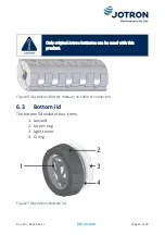
Page 15: ...y original Jotron batteries can be used with this product Figure 6 Illustration Battery module no cable or connector 6 3 Bottom lid The bottom lid includes four items 1 Lanyard 2 Screen ring 3 Light t...

Page 16: ...lifeboat liferaft 7 1 Brackets There are two different mounting brackets available Wall bracket Lifeboat bracket with or without a pipe clamp 7 1 1 Mounting the wall bracket A wall bracket is delivere...

Page 17: ...Doc No 84145 Rev L jotron com Page 17 of 40 Figure 9 Illustration Tron SART20 mounted in wall bracket Figure 10 Illustration Placement of Tron SART20 in a wall mount...

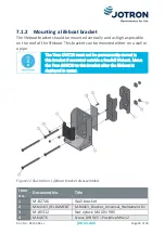
Page 18: ...l or a pipe The Tron SART20 must not be permanently stored in this bracket if mounted outside a freefall lifeboat Move the Tron SART20 to this bracket after the lifeboat is deployed in water Figure 11...

Page 19: ...DIN 965 Pozidrive M6x90 7 M 84838 Pipe clamp 13 M 84875 Washer plate 14 M 91469 Nu nylock M6 DIN 985 15 M 82275 Washer DIN 9021 6mm Table 1 List of components lifeboat bracket Use the following dimens...

Page 20: ...No 84145 Rev L jotron com Page 20 of 40 Figure 13 Illustration Mounting interior exterior wall The lifeboat bracket fits a pipe with a maximum diameter of 50mm Figure 14 Illustration Mounting on a pi...

Page 21: ...y on a pipe Figure 16 Illustration Placing the Tron SART20 into the lifeboat bracket 7 2 Non bracket mounting options A Tron SART20 can be mounted on a lifeboat liferaft without a bracket in several w...

Page 22: ...e lanyard to tie the Tron SART20 to any object inside the liferaft where the unit can hang freely Keep the Tron SART20 away from any metal objects To mounting the lanyard do the following 1 Remove the...

Page 23: ...to an inflatable canopy To use the Liferaft mounting strap do the following 1 Attach the strap to the fastening ring on the top of the Tron SART20 2 Fasten the other end of the strap to the canopy Fig...

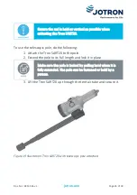
Page 24: ...he following 1 Attach the Tron SART20 to the pole 2 Extend the pole to its full length and lock it in place Make sure the pole is locked by pulling hard when it is fully extended The pole can be faste...

Page 25: ...how to change the battery on the Tron SART20 7 3 1 Disassembly To disassemble the battery module do the following 1 Twist the rubber grip anticlockwise to remove the lid If difficult remove the rubbe...

Page 26: ...he two old 5gram silica gel bag 7 3 2 Assembly To assemble the battery module do the following 1 Install the new battery verify the cable is within the guide 2 Connect the cable to the electronics bla...

Page 27: ...tron com Page 27 of 40 4 Mount the rubber holder 5 Remove old O ring using for example a plastic card Use Vaseline acid free and fit a new O ring in place 6 Reinstall the lid tighten by hand then repl...

Page 28: ...perating instructions label The Tron SART20 should only be used in an emergency The battery lasts for 96 hours from activation Replace the battery if the unit is used for any purpose other than a test...

Page 29: ...The Tron SART20 requires the following maintenance Timing Requirements Every month Both the unit and the bracket should be inspected The unit should be removed from the bracket and tested Perform insp...

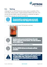
Page 30: ...onducted in open sea to avoid interference on the radar display from land echoes 1 Move the switch to the TEST position and hold Simultaneously a person should observe the radar display to check for c...

Page 31: ...not indicate an error in the unit Placing it further away will reduce the signals to 12 dots on the radar display showing the direction to the unit Typical display when Tron SART20 is located near 0 2...

Page 32: ...com Page 32 of 40 selected on the radar the text SART is shown at the bottom of the display Ensure the SART feature is turned off when SART detection is no longer necessary Figure 22 Image Tron SART2...

Page 33: ...Doc No 84145 Rev L jotron com Page 33 of 40 10 Test and maintenance records Below is an overview of all test and control details Date B T Signature Inspector name B New battery T Test...

Page 34: ...ensure the batteries are isolated from combustibles A short circuit for a few seconds will not seriously affect the battery A prolonged short circuit will cause the battery to lose energy generate si...

Page 35: ...m x 89mm x 89mm Weight 480grams Temperature operating 20 C to 55 C 4 F to 131 F Temperature storage 30 C to 65 C 22 F to 149 F Operating life 96 hours standby 8 hours continuous operation at 20 C Lany...

Page 36: ...s for this product refer to jotron com 14 Spare parts For an overview of the available spare parts for this product refer to jotron com 14 1 Counterfeit spare parts Ensure that all spare parts being f...

Page 37: ...rking and battery exchange are provided by an authorized Jotron service agent Improper service or maintenance may destroy the functionality and or performance of this product Jotron does not accept an...

Page 38: ...15 16 ES E 14 08 2008 Battery label pages 9 13 21 ES F 12 02 2009 Brackets and layout pages 10 13 19 new total is 28 pages TH G 16 12 2009 Added text page 24 ES H 05 11 2010 Added information pages 2...

Page 39: ...Doc No 84145 Rev L jotron com Page 39 of 40...

Page 40: ...64 Tel 65 65 42 63 50 USA Jotron USA Inc 6300 Rothway Street Suite C Houston TX 77040 USA Tel 1 713 268 1061 UK Jotron UK Ltd Crosland Park Cramlington NE23 1LA UK Tel 44 1670 712000 CHINA Norway Jotr...

Reviews: