


Page 2 of 3
1770 Hayes Street
Grand Haven, MI 49417
www.jostinternational.com
The right to alter specifications is reserved.
Ph. (616) 846-7700 (800) 253-5105
Fax (616) 846-0310
LT SK37H-01 Rev.H
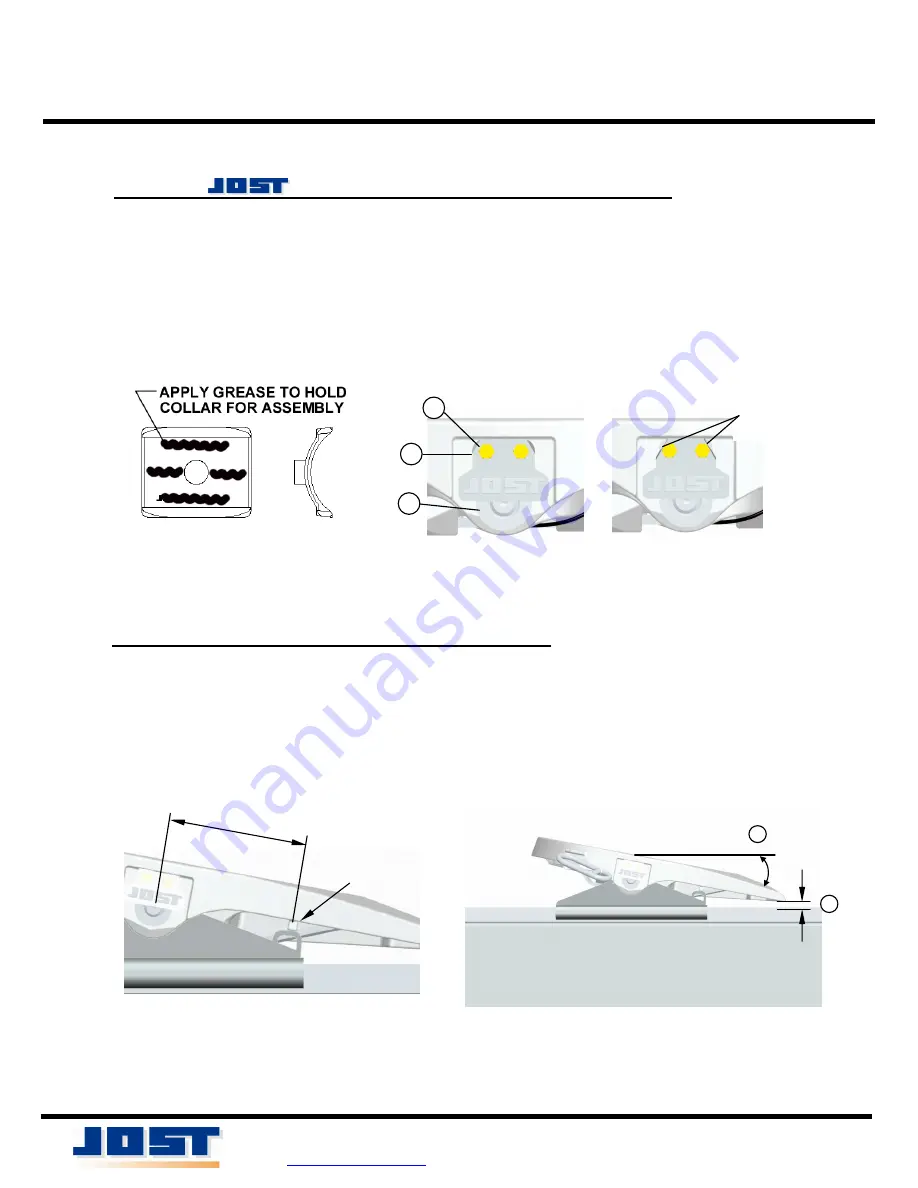
C. INSTALL MODEL JSK 37H TOPPLATE (CONT.):
6. Using a suitable lifting device, lower the new Jost topplate onto the
mounting bracket.
7. Install the pivot pins (figure 4 item 3) aligning the flange with the
threaded holes in the topplate casting.
8. Align a locking tab (item 2) with each pivot pin and install the hex head
cap screws (item 1) thru the locking tabs, the pivot pin flange and into
the topplate casting ears.
9. Bend the locking tabs over each cap screw as shown in figure 4.
FIGURE 3
FIGURE 4
D. VERIFY MOUNTING BRACKET TILT STOPS:
1. The topplate casting lugs must rest squarely on the mounting bracket tilt
stops. (see figure 5)
2. The topplate tilt angle must be 20 degrees or less. (figure 6 item 1)
3. The tails of the topplate must not contact the frame rails or the slide bed.
(item 2)
4. Modify the mounting bracket tilt stops as needed.
1
2
FIGURE 5
FIGURE 6
8-3/4”
1
2
3
BEND TABS
AFTER TIGHTENING
CASTING LUG
GAP