background image

19

SERVICE AND ADJUSTMENTS

D

C

G

E

F

M

L

K

R

Q

A

P

G

B

FIG. 19

TO INSTALL MOWER (See Fig. 19–22)

Be sure tractor is on level surface and engage park ing 

brake.
•  Lower attachment lift lever to it's lowest position.

CAUTION: LIFT LEVER IS SPRING 

LOADED. HAVE A TIGHT GRIP ON 

LIFT LEVER, LOWER IT SLOWLY AND 

ENGAGE IN LOWEST POSITION.

NOTE:

 Be sure mower side suspension arms (A) are point-

ing forward before sliding mower under tractor.
•  Slide mower under tractor until it is centered under 

tractor. 

• 

ATTACH MOWER SIDE SUSPENSION ARMS (A) TO 

CHASSIS - Position hole in arm over pin (B) on outside 

of tractor chassis and secure with retainer spring.

•  Repeat on opposite side of tractor.

TO REMOVE MOWER (See Fig. 19)

•  Place attachment clutch in “DIS EN GAGED” position.
•  Lower attachment lift lever to its lowest position.
•  Roll belt off engine pulley (M) and belt keepers (G).
• 

Remove retainer spring (K), slide col lar (L) off and push 

housing guide (P) out of brack et.

•  Remove clutch cable spring (Q) from idler arm (R).
• 

Disconnect front link (E) from mower - remove retainer 

spring and washer.

•  Go to either side of mower and disconnect mower 

suspension arm (A) from chassis pin (B) and rear lift 

link (C) from rear mower bracket (D) - remove retainer 

springs and washers. 

CAUTION: AFTER REAR LIFT LINKS 

ARE DISCONNECTED, THE ATTACH-

MENT LIFT LEVER WILL BE SPRING 

LOADED. HAVE A TIGHT GRIP ON LIFT 

LEVER WHEN CHANGING POSITION 

OF THE LEVER.

•  Slide mower out from under right side of tractor.

IMPORTANT:

 IF AN ATTACHMENT OTHER THAN THE 

MOWER IS TO BE MOUNTED ON THE TRAC TOR, 

REMOVE THE FRONT LINK (E) AND REAR LIFT LIKS 

(C) FROM TRACTOR AND HOOK THE CLUTCH SPRING 

(Q) INTO THE CABLE GUIDE ON FRONT EDGE OF 

LOWER DASH.

WARNING: TO AVOID SERIOUS INJURY, BEFORE PERFORMING ANY SER VICE OR AD JUST -

MENTS:

  Depress brake pedal fully and set parking brake.

  Place attachment clutch  in “DISENGAGED” position.

  Turn ignition key to “STOP” and remove key.

  Make sure the blades and all moving parts have completely stopped.

  Disconnect spark plug wire from spark plug and place wire where it cannot come in contact  

 with 

plug.

Summary of Contents for LT2217 A

Page 1: ...03076 Operator s Manual J O N S E R E D S E R V I C E LT2218A ...

Page 2: ...ing brake stop engine and remove keys before dismounting Disengage blades when not mowing Shut off engine and wait for all parts to come to a complete stop before cleaning the machine removing the grass catcher or unclogging the discharge guard Operate machine only in daylight or good artificial light Do not operate the machine while under the influence of alcohol or drugs Watch for traffic when o...

Page 3: ...ach towed equipment except at the hitch point Follow the manufacturer s recommendation for weight limits for towed equipment and towing on slopes Never allow children or others in or on towed equip ment On slopes the weight of the towed equipment may cause loss of traction and loss of control Travel slowly and allow extra distance to stop V SERVICE SAFE HANDLING OF GASOLINE To avoid personal injur...

Page 4: ... proper tools to service or repair this tractor Please read and retain this manual The instructions will enable you to assemble and maintain your tractor properly Always observe the SAFETY RULES CUSTOMER RESPONSIBILITIES Read and observe the safety rules Follow a regular schedule in maintaining caring for and using your tractor Follow the instructions under Maintenance and Stor age sections of thi...

Page 5: ... previously removed Tighten securely Snap steering wheel insert into center of steering wheel Remove protective materials from tractor hood and grill Your new tractor has been assembled at the factory with the exception of those parts left unassembled for shipping purposes TO REMOVE TRACTOR FROM CARTON UNPACK CARTON Cut along dashed lines on all four panels of carton Remove end panels and lay side...

Page 6: ...ltandflatwashersecuringseattocardboard packing and set aside for assembly of seat to tractor Remove the cardboard packing and discard Connect switch to seat Place seat on seat pan so all three 3 bottom pads are positioned over large slotted holes in pan WIRING HARNESS SEAT SWITCH PAD TAPE SEAT PAN SLOT Push down on seat to engage pads in slots and pull seat towards rear of tractor Raise seat and t...

Page 7: ... instructions See TO START ENGINE and PURGE TRANSMISSION in the Operation section of this manual TO DRIVE TRACTOR OFF SKID See Op eration section for location and function of controls Be sure all the above assembly steps have been com pleted Check engine oil level and fill fuel tank with gasoline Place freewheel control in transmission engaged position see TO TRANSPORT in Operation section of this...

Page 8: ...entify safety inform ation about hazards which can result in death serious injury and or property damage DANGER indicates a hazard which if not avoided will result in death or serious injury WARNING indicates a hazard which if not avoided could result in death or serious injury CAUTION indicates a hazard which if not avoided might result in minor or moderate injury CAUTION when used without the al...

Page 9: ...E Locks clutch brake pedal into the brake position D THROTTLE CONTROL Used to control engine speed E ATTACHMENT CLUTCH SWITCH Used to engage the mower blades or other attachments mounted to your tractor F IGNITION SWITCH Used for starting and stopping the engine G REVERSE OPERATION SYSTEM ROS ON POSITION Allows operation of mower or other powered attachment while in reverse H LIGHT SWITCH Turns th...

Page 10: ... Fig 6 The direction and speed of movement is controlled by the forward and reverse drive pedals Start tractor and release parking brake Slowly depress forward I or reverse J drive pedal to begin movement Ground speed increases the further down the pedal is depressed FIG 8 STOPPING MOWER BLADES To stop mower blades push attachment clutch switch in to disengaged position o GROUND DRIVE To stop grou...

Page 11: ...our tractor is equipped with a Reverse Operation System ROS Any attempt by the operator to travel in the reverse direction with the attachment clutch engaged will shut off the engine unless ignition key is placed in the ROS ON position WARNING Backing up with the attachment clutch en gaged while mowing is strongly discouraged Turning the ROS ON to allow reverse operation with the attachment clutch...

Page 12: ...ake and brake pedal Slowly depress appropriate drive pedal to slowest set ting Make all turns slowly USING THE REVERSE OPERATION SYSTEM Only use if you are certain no children or other bystanders will enter the mowing area Depress brake pedal all the way down Withenginerunning turnignitionkeycounterclockwise to ROS ON position Look down and behind before and while backing Slowly depress reverse dr...

Page 13: ... for approximately five feet then backwards for five feet Repeat this driving procedure three times Your transmission is now purged and now ready for normal operation TO START ENGINE See Fig 6 When starting the engine for the first time or if the engine has run out of fuel it will take extra cranking time to move fuel from the tank to the engine Be sure freewheel control is in the transmission en ...

Page 14: ...s mow in the opposite direction making left hand turns until finished See Fig 14 If grass is extremely tall it should be mowed twice to reduce load and possible fire hazard from dried clip pings Make first cut relatively high the second to the desired height Do not mow grass when it is wet Wet grass will plug mower and leave undesirable clumps Allow grass to dry before mowing Always operate engine...

Page 15: ...s not cover items that have beensubjectedtooperatorabuseornegligence Toreceive full value from the warranty operator must maintain tractor as instructed in this manual Some adjustments will need to be made periodically to properly maintain your tractor At least once a season check to see if you should make any of the adjustments described in the Service and Adjustments section of this manual At le...

Page 16: ...ion OPERATOR PRESENCE SYSTEM AND REVERSE OP ERATION SYSTEM ROS Be sure operator presence and reverse operation systems are working properly If your tractor does not function as described repair the problem immediately The engine should not start unless the brake pedal is fully depressed and the attachment clutch control is in the disengaged position CHECK OPERATOR PRESENCE SYSTEM Whentheengineisru...

Page 17: ...t least once a year if the tractor is not used for 50 hours in one year Check the crankcase oil level before starting the engine and after each eight 8 hours of operation Tighten oil fill cap dipstick securely each time you check the oil level TEMPERATURE RANGE ANTICIPATED BEFORE NEXT OIL CHANGE SAE VISCOSITY GRADES 20 0 30 40 80 100 30 20 0 20 30 40 F C 32 10 10 60 5W 30 SAE 30 oil_visc_chart1_e ...

Page 18: ...transmission will shorten the useful life of your tractor Use compressed air or a leaf blower to remove grass leaves and trash from tractor and mower IN LINE FUEL FILTER See Fig 18 The fuel filter should be replaced once each season If fuel filter becomes clogged obstructing fuel flow to carburetor replacement is required With engine cool remove filter and plug fuel line sec tions Place new fuel f...

Page 19: ...t of bracket Remove clutch cable spring Q from idler arm R Disconnect front link E from mower remove retainer spring and washer Go to either side of mower and disconnect mower suspension arm A from chassis pin B and rear lift link C from rear mower bracket D remove retainer springs and washers CAUTION AFTER REAR LIFT LINKS ARE DISCONNECTED THE ATTACH MENT LIFT LEVER WILL BE SPRING LOADED HAVE A TI...

Page 20: ...etainerspring K Install belt on engine pulley M in belt keepers G IMPORTANT CHECK BELT FOR PROPER ROUTING IN ALL MOWER PULLEY GROOVES Raise attachment lift lever to highest position If necessary adjust gauge wheels before operating mower as shown in the Operation section of this manual E F H J A B ATTACH FRONT LINK E Work from left side of trac tor Insert rod end of link assembly through front hol...

Page 21: ... side of mower or to the right to raise LH side of mower NOTE Each full turn of adjustment nut will change mower height about 3 16 Test your adjustment by mowing some uncut grass and visually checking the appearance Readjust if necessary until you are satisfied with the results PRECISION SIDE TO SIDE ADJUSTMENT See Fig 24 With all tires properly inflated park tractor on level ground or driveway CA...

Page 22: ...ss A Remove anti rotation link B on right side of tractor Remove belt from stationary idler C and clutching idler D Remove belt from centerspan idler E Pull belt slack toward rear of tractor Carefully remove belt upwards from transmission input pulley and over cooling fan blades F Removebeltdownwardfromenginepulleyandaround electric clutch G Slide belt toward rear of tractor off the steering plate...

Page 23: ...xle cover retaining ring and washers to allow wheel removal rear wheel contains a square key Do not lose Repair tire and reassemble On rear wheels only align grooves in rear wheel hub and axle Insert square key Replace washers and snap retaining ring securely in axle groove Replace axle cover NOTE To seal tire punctures and prevent flat tires due to slow leaks tire sealant may be purchased from yo...

Page 24: ...t at the factory and ad justment should not be necessary If adjustment is neces sary see engne manual TO ADJUST CARBURETOR Your carburetor is not adjustable If your engine does not operate properly due to suspected carburetor problems take your tractor to an authorized service center for repair and or adjustment FIG 33 02021 02182 FIG 31 FIG 32 SEAT PAN BATTERY BOX DOOR KEPS NUT HEX BOLT POSITIVE ...

Page 25: ...FUELSYSTEMPARTSSUCH AS CARBURETOR FUEL FILTER FUEL HOSE OR TANK DURING STORAGE ALSO EXPERIENCE INDICATES THAT ALCOHOL BLENDED FUELS CALLED GASOHOL OR USING ETHANOLORMETHANOL CANATTRACTMOISTUREWHICH LEADSTOSEPARATIONANDFORMATIONOFACIDSDURING STORAGE ACIDIC GAS CAN DAMAGE THE FUEL SYSTEM OF AN ENGINE WHILE IN STORAGE Empty the fuel tank by starting the engine and let it run until the fuel lines and ...

Page 26: ... Check all wiring 7 Faulty ignition switch 7 Check replace ignition switch 8 Faulty solenoid or starter 8 Check replace solenoid or starter 9 Faulty operator presence switch es 9 Contact an authorized service center department Engine clicks but will not 1 Weak or dead battery 1 Recharge or replace battery start 2 Corroded battery terminals 2 Clean battery terminals 3 Loose or damaged wiring 3 Chec...

Page 27: ... air pressure 5 Check tires for proper air pressure 6 Worn bent or loose blade 6 Replace blade Tighten blade bolt 7 Buildup of grass leaves and trash under mower 7 Clean underside of mower housing 8 Mower drive belt worn 8 Replace mower drive belt 9 Blades improperly installed 9 Reinstall blades sharp edge down 10 Improper blades used 10 Replace with blades listed in this manual 11 Clogged mower d...

Page 28: ...28 SERVICE NOTES ...

Page 29: ...29 SERVICE NOTES ...

Page 30: ...30 SERVICE NOTES ...

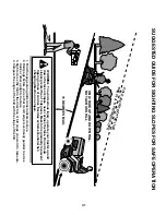
Page 31: ... never across the face Do not mow slopes greater than 15 degrees Make turns gradually to prevent tipping or loss of control Exercise extreme caution when changing direction on slopes 1 Fold this page along dotted line indicated above 2 Hold page before you so that its left edge is vertically parallel to a tree trunk or other upright structure 3 Sight across the fold in the direction of hill slope ...

Page 32: ...Jonsered Motor AB S 433 81 Partille Sweden 532 41 18 70 02 28 07 CL Printed in U S A ...

Reviews: