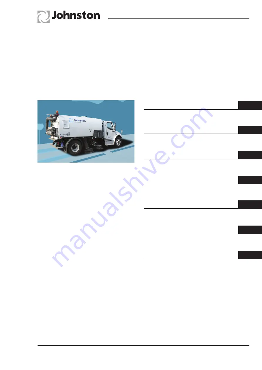
background image

Johnston Sweepers Limited

General Arrangement

Controls

Operation

Optional Equipment

Chapter not used

Routine Maintenance

RT655 Mk III

Regenerative Air

Twin Engine

Suction Sweeper

From Manufacture Sequence No. 7458

Part No 01288-1(GB)

Revision Level A

E.C.N. 712675

Print date - 16/11/2015


1


2


3


4


5


6

Operator’s 

Guide

Conformity Certificates


7

Summary of Contents for RT655

Page 1: ...onal Equipment Chapter not used Routine Maintenance RT655 Mk III Regenerative Air Twin Engine Suction Sweeper From Manufacture Sequence No 7458 Part No 01288 1 GB Revision Level A E C N 712675 Print d...

Page 2: ...sment 12 End of day cleaning of body and machine Johnston Sweepers Limited can provide operator training upon request We would point out that it is the employers responsibility to carry out his own Ri...

Page 3: ...BROOMVAK are registered trade marks of Johnston Sweepers Limited All copyrights and rights reserved The reproduction distribution and utilisation of this document as well as the communication of its...

Page 4: ...OG1 4 A OG2 1 A OG2 2 A OG2 3 A OG2 4 A OG2 5 A OG2 6 A OG2 7 A OG2 8 A OG3 1 A OG3 2 A OG3 3 A OG3 4 A OG3 5 A OG3 6 A OG3 7 A OG3 8 A OG3 9 A OG3 10 A OG3 11 A OG3 12 A OG4 1 A OG4 2 A OG4 3 A OG4 4...

Page 5: ...eaner instructions i e use only genuine Johnston replacement air cleaner elements and refer to Chapter 6 of this guide for servicing instructions RTOG 049 4 1a 2 3 1b 4 INTERNATIONAL SYMBOLS Conformin...

Page 6: ...ap while fan is running Never reach in or drop tools into the fan case Release radiator cap carefully when hot to avoid scalding Stay at least 1 metre distance from the machine Wear ear defenders when...

Page 7: ...RT655 Operator s Guide CHAPTER 1 Johnston Sweepers Limited General Arrangements Chapter General Arrangement Page Issue A Table of Contents Subject Page General Arrangement General Arrangement Drawing...

Page 8: ...eral Arrangement Page Issue A 29 16 17 32 35 30 30 31 30 13 10 7 4 20 18 19 15 29 1 8 26 13 25 27 1 5 6 34 Cold Weather Drains RTOG 051 2 8 11 9 21 2 12 14 37 3 22 34 23 26 36 33 28 24 30 GENERAL ARRA...

Page 9: ...ilter screen water sprays 6 18 SepaVac separator box 3 19 SepaVac access panel 20 SepaVac discharge door 3 21 SepaVac water flush 3 22 SepaVac water flush hydrant connection 3 23 R H Water tank and co...

Page 10: ...RT655 Operator s Guide OG1 4 Chapter General Arrangement Page Issue A...

Page 11: ...rs Limited Controls Chapter Controls Table of Contents Subject Page Operating Controls In Cab Switch Panel OG2 2 Cab Mounted Controls OG2 6 Operating Controls External Load Discharge Control Pendant O...

Page 12: ...ter Controls Page Issue A Sweeping Controls Switch Panel 1200 2200 15hrs RTOG 042 Src Eng SPN00000 A B C1 C2 D1 E1 F G E2 D2 J1 K1 M O R T1 U V W Y B1 B3 B4 B6 B5 B7 B2 T2 X Q K1 J2 K2 K3 L N S1 S2 P1...

Page 13: ...in C2 RH Variabrush spring centred switch moves brush out or in E1 E2 LH RH Gutter Broom 2 position switch stowed active illuminated when selected D1 LH Rotatilt spring centred switch alters angle of...

Page 14: ...ide OG2 4 Chapter Controls Page Issue A Sweeping Controls Switch Panel 1200 2200 15hrs RTOG 042 Src Eng SPN00000 A B C1 C2 D1 E1 F G E2 D2 J1 K1 M O R T1 U V W Y B1 B3 B4 B6 B5 B7 B2 T2 X Q K1 J2 K2 K...

Page 15: ...spring centred switch REDUCE OFF INCREASE R Beacons 2 position switch OFF ON illuminated when selected N Hood reverse pick up select switch 2 position switch OFF ON O Rear Worklamp 2 position switch...

Page 16: ...es brush speed BB Pressure control for each gutter broom Powasave clockwise rotation reduces brush pressure CC Fuse box is mounted inside relay box Fuse functions see page OG2 8 DD Load discharge pend...

Page 17: ...e the driver s seat Switch Function M02OG 005 Opens rear door Closes rear door Raises body Lowers body Stows body prop when body is raised and not resting on it Green safety switch must be pressed to...

Page 18: ...SUPAWASH CONTROLS VEG SENSORS POWER VEG GATE AUX ENGINE IGNITION AUX ENGINE CRANK AUX ENGINE ECU POWER BEACONS Fuse No Function Amps F1 Beacons 20 F2 Marker Lights 10 F3 Power I O Node 20 F4 Water Su...

Page 19: ...e OG3 2 Engine Engine Starting and Operation Procedures John Deere OG3 3 Sweeping Commence Sweeping OG3 5 Hood Hop OG3 6 Interrupt Sweeping OG3 6 Terminate Sweeping OG3 6 Water Drainage OG3 6 Blocked...

Page 20: ...road wheels However it is necessary to ascertain the centre of gravity as it can be up to 20 from the mid point of the wheelbase The exact position is dependent upon chassis type and vehicle build To...

Page 21: ...ff NB The chassis ignition switch must be turned on to energise the switch panel Never engage engine cranking for longer than 60 seconds as this can damage the starter motor John Deere Electronic Engi...

Page 22: ...e button Q need pushing to increase engine RPM higher than 1500 NB If the truck and auxiliary engine use a single fuel tank When the fuel gauges reaches full stop the auxiliary engine as there is a ch...

Page 23: ...it the debris being swept J2 K2 Always operate K3 body interior sprays 9 Commence sweeping at a forward speed between 2 12 kph depending upon the debris being swept Always use the slowest channel brus...

Page 24: ...on Driving the sweepgear with the brush es or Hood down in this position could lead to irreparable damage When stopping the auxiliary engine the throttle automatically returns to tick over Should the...

Page 25: ...ck up head trunking or inlet tube is blocked 6 With the vehicle on level ground carefully raise the body and rest it on the body prop ensure the prop has located against the locking step on the subfra...

Page 26: ...ensure the following safety aspects are observed Ensure the machine is standing on firm level ground and there are no obstructions above or to the rear before raising the body The rear door must be fu...

Page 27: ...oor with the washdown hose or Supawash hand lance whichever is fitted to remove any caked material B A RTOG 009 5 C A bang should be heard when the rear door locking pin locates in the latch plate A w...

Page 28: ...ith the underside of the nozzle hood and the nozzle suction hose 3 After about 5 minutes lower the hood to the ground and continue the flushing cycle This will collect all the water into the body flus...

Page 29: ...Care must be taken to ensure water sprayed onto the road does not freeze Do not use full suction capacity above 1600 engine rpm as the air speed up the nozzle could cause the water to freeze Operating...

Page 30: ...overrides B open and the Supawash spraybar if fitted on Manual override indicator C The Supawash pump will stop when the water low level light illuminates 3 Open the Pressadrain tap A for 1 minute to...

Page 31: ...Guide CHAPTER 4 Johnston Sweepers Limited Optional Equipment Chapter Optional Equipment Table of Contents Subject Page Options Supawash OG4 2 Wanderhose OG4 4 Emergency Discharge OG4 6 Emergency Hood...

Page 32: ...fety goggles is recommended in case of deflected spray debris NEVER direct a high pressure nozzle at the skin as the fluid may penetrate the underlying tissue etc and cause serious injury Safety Preca...

Page 33: ...clean down the vehicle at the end of a shift or day s work OPERATION The auxiliary engine must be running and the throttle adjusted to 2000 rpm Press switch M1 on the switch panel to activate the wat...

Page 34: ...een blanked 1 Before using the Wanderhose always fully open the VEG gate 2 Raise the body and blank off suction duct 3 Switch the ECO override button so full throttle RPM is available 4 Unclip the Wan...

Page 35: ...ngine speed control in the cab to maximum speed releasing it will return speed to the preset value The hose and boom are hydraulically lifted and can be used to the left or right hand side of a statio...

Page 36: ...eper ignition 3 Use discharge pendant to raise body or open rear door EMERGENCY HOOD LIFT To raise the hood without the auxiliary engine running or if the engine malfunctions when the hood is in the w...

Page 37: ...t OG6 7 Pick up Hood OG6 8 Spring Adjustments OG6 9 Suction Fan Impeller and Casing OG6 10 Filter Screens and Roof Duct OG6 10 Water Filter Cleaning OG6 11 Auxiliary Engine OG6 12 Cold Weather Precaut...

Page 38: ...firm level ground and there are no obstructions above or to the rear before raising the hopper Ensure that the body is resting on the body prop before working underneath the raised hopper Keep hands...

Page 39: ...ited Chapter Routine Maintenance Page Issue A Key D Daily W Weekly A 500 Hours B 1000 Hours C 12 Monthly Attention is drawn to the recommendations for servicing in the Auxiliary Engine Handbook MAINTE...

Page 40: ...uld be tensioned just enough to allow the skids to lightly contact the road surface If the spring tension is inadequate the hood will drag heavily on the road surface resulting in premature skid wear...

Page 41: ...rrect operation of jets and any plunger seal leakes Service as necessary Service B every 1000 hours 1 Carry out 500 hour service plus 2 Renew hydraulic return filter element 3 Renew water pump suction...

Page 42: ...by using either the mechanical stop or the Variabrush control Maintain a visual eye on its position when sweeping so as to avoid other road traffic The Gutter Broom s are supported on a forward facing...

Page 43: ...maintain optimum brush angle This can be adjusted as shown below Channel Brush Replacement Ensure the auxiliary engine is not running and isolated before maintenance or replacement is attempted Sharp...

Page 44: ...by three locking nuts and one bolt that locates into the rear side assembly skate The initial setting of the skate is on the centre line of the skate side slots and the skate can be lowered as it wear...

Page 45: ...factory is set for light sweeping with one chain link spring connection Once set this does not normally need to be adjusted RTNZ 003 Heavy Medium Light The settings can be 30 50mm The factory setting...

Page 46: ...n up as a thinning of the blades generally in a broad wear pattern A Once apparent thinning of the impeller blades is observed the component must be replaced when any blade thickness E is less than 2m...

Page 47: ...e shut off valve actuator A located on the bottom of the filter It has a bayonet type mechanism Press up and turn anti clockwise to position i to shut the valve 2 To access the filter element unscrew...

Page 48: ...s are shown in the lubrication diagram see later in this chapter The oil is best drained whilst warm via the remote drain plug C Cold Weather Precautions The cooling system D must be filled with equal...

Page 49: ...at the intervals given in the Maintenance Schedule D A B C RTOG 019 1 Ensure that the elements lid and clips are correctly fitted and that the air intake pipe and clips to the engine are in good condi...

Page 50: ...ge blemishes or build up of material such as tar cement paint etc The rods can be cleaned with fine wire wool and or spirit to ensure long seal life When cleaning the machine avoid playing the washdow...

Page 51: ...l is introduced via filler port C The pump oil is drained via either of plugs D The oil colour should be clear if it is frothy milky when seen through window A then water has entered the oil and it sh...

Page 52: ...ce Schedules for lubrication intervals LUBRICATION DIAGRAM 2 i 3 RTOG 054 G A C E F 1 1 Body prop Ensure autoprop has engaged when body is raised 2 Filter regulator unit FR i Isolation valve 3 Water p...

Page 53: ...8 0L ACEA E3 E5 94 23 5 Titan Cytrac HSY 75W 90 B Gearbox H Supawash Pump 2 50L 0 37L GL 4 63684 5 C Hydraulic System D Fluid Flywheel 80L 4 85L 39677 5 E Chassis PAS F Auto Gearbox 94 67 1 G Antifre...

Page 54: ...RT655 Operator s Guide OG6 18 Chapter Routine Maintenance Page Issue A...

Page 55: ...ston Sweepers Limited Conformity Certificates Chapter Conformity Certificates Table of Contents Subject Page EC Declaration of Conformity Certificates Safety Requirements OG7 2 Noise Engines OG7 3 Noi...

Page 56: ...Declares that Product Name Johnston Road Surface Cleaner Product Type s VT501 VT651 VT801 VS501 VS651 VS801 ES351 RT655 Product Options All Product Serial Number Conforms to the following standards E...

Page 57: ...owing equipment conforms to the requirements of EC Directive 2000 14 EC Description of Equipment EC Directive 2000 14 EC Annex 1 Item 46 Power sweeper Product Name and Johnston RT655 chassis mounted p...

Page 58: ...th 2002 42 EC as amended Hand Arm The vector sum weighted root mean square acceleration values ah w during recommended sweeping washing activities do not exceed 2 5 m s2 Whole Body The dominant axis w...

Reviews: