background image

27

CHAPTER 5:TROUBLESHOOTING

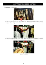
Check point:

2) Motor check

Select auto course ,after execute , the machine core will going down.If the machine core goes

down ,the U/D motor is good .

If not,disconnect the connector of U/D motor , and take the connector of Tap motor to connect.

Take the terminal off.

Summary of Contents for MC-J6900

Page 1: ...sue Date 2018 4 23 Edition 01 Doc No Revision Date Edition Time 2018 1 0 10 Page 47 Johnson Industries Shanghai Co Ltd MC J6900 MASSAGE CHAIR Service Manual Approval Review Editor Allen Sun Allen Sun...

Page 2: ...static discharge ground wire if it is required to directly contact the baseplate when performing operations or touch the ground wire ground wires of fridges washing machines etc with bare hands to dis...

Page 3: ...ue 17 5 4 Pushrod Motor Does Not Work 19 5 5 Speak Has No Sound 19 5 6 Individual Air Bag Can Not Be Inflated Or Inflated Sufficiently 19 5 7 All Air Bags Do Not Work 19 5 8 Abnormal Warming Function...

Page 4: ...1 CHAPTER 1 PRODUCT SPECIFICATIONS...

Page 5: ...2 CHAPTER 1 PRODUCT SPECIFICATIONS...

Page 6: ...3 CHAPTER 1 PRODUCT SPECIFICATIONS...

Page 7: ...the plastics or the pipes and then wipe with a dry cloth to completely remove the residual detergent Wipe the coated surface with a dry cloth Do not use benzene thinner alcohol solvents or abrasives...

Page 8: ...RUCTION 3 1 Key operation A When the power is on and manual controller is not yet activated before enter the main interface press point and heat on the manual controller at the same time for 5 seconds...

Page 9: ...P8 PU E In mode selection state press OK to enter the mode to operate the massage chair F After mode selection use up and down again to select the element to be controlled such as A0 A5 G After eleme...

Page 10: ...he selected element forward or reverse if such element has no forward and reverse states it will be in motion state I After entering the mode press stop key to return to the previous layer of menu thi...

Page 11: ...8 CHAPTER 3 ENGINEERING MODE INSTRUCTION Mode list 3 3 P1 Mode Motor test mode is mainly used to test if each motor works normally and to adjust chair angle when replacing elements...

Page 12: ...massage intensity 100 500 and motion menu LCD sensing position display window will indicate whether the limit switch is triggered The left figure shows that the upper limit is reached when the selecte...

Page 13: ...e returned number exceeds 100 the carrying digit will display massage intensity 100 500 D3 is a major test item if the intensity is set to medium air bag strength 2 and machine core forward value is g...

Page 14: ...ON 3 6 P4 Mode Air bag testing is mainly used to test if the air bag works normally the inflation rate is normal there is leakage etc It can also distinguish the position of the air bag to be tested v...

Page 15: ...ow displays U0 to enter manual controller software version check function c Press air pressure strength key and the time window displays in a jumping loop of v1 04 v1 04 indicating that the manual con...

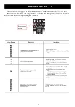
Page 16: ...code will appear on the machine s manual controller and the machine will stop Maintenance personnel can judge the fault conditions and anticipate maintenance materials based on the error code reporte...

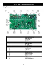
Page 17: ...14 CHAPTER 5 TROUBLESHOOTING 5 1 Wiring Schematic...

Page 18: ...air motor 3 Foot motor 4 Foot heat 5 Power 6 Back chair heat 7 Air pump 8 12 ways air valve 9 5 ways air valve 10 Right speaker 11 Left speaker 12 Audio sub 13 Bluetooth board 14 Remote controller 15...

Page 19: ...on the switch 3 Press the button on the remote controller 4 Select a massage function If the above mentioned make no effects reset the machine 1 After reset the power led turns on so it may be motor...

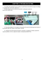
Page 20: ...cting line The main purpose is to measure if the input end voltage has output voltage AC110V or AC220V after passing through the filter if there is no voltage check if the fuse is burned The power mus...

Page 21: ...side the transformer is damaged replace the transformer 1000347562 3 Record the software for the master control panel and manual controller again and observe if the indicator light of the master contr...

Page 22: ...5 6 Individual Air Bag Can Not Be Inflated Or Inflated Sufficiently Solution Use engineering mode P4 to detect and refer to the air bag location diagram Check if the solenoid valve works normally Chec...

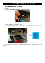
Page 23: ...erminal connection is normal 2 Check warming piece s resistance value Back chair warming piece normally about 17 and about 34 in case of unilateral damage Check connecting line replace warming piece I...

Page 24: ...g piece normally about 48 and about 96 in case of unilateral damage Check connecting line replace warming piece 1000373418 1000405385 3 Measure if the master control panel has DC24V 30V output if not...

Page 25: ...motor triggers the limit For example when the front and back machine core motors cannot move forward it is required to note that if the front limit lamp signal is triggered when the front limit lamp...

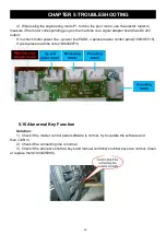
Page 26: ...no check motor power line power line PASS replace master control panel 1000391515 If yes replace machine core 1000382973 5 10 Abnormal Key Function Solution 1 Check if the master control panel softwa...

Page 27: ...000228108 If the frequency is low press the keys to return to the original state and then observe 2 Check if the manual controller s keys are seized 5 12 Machine Core Movement Issue Symptom Normally i...

Page 28: ...he limit lamp signal is triggered when the machine core does not touch the upper lower limit it represents sensor anomaly or poor contact of the signal line 1000306155 Note When the machine core s old...

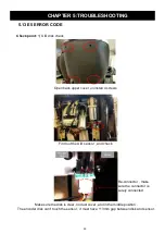
Page 29: ...ING 5 13 E5 ERROR CODE Check point 1 U D disk check Open back upper cover uninstall 4 screws Find out the U D sensor and check Make sure the disk is clear no dust cover and in the middle position The...

Page 30: ...Motor check Select auto course after execute the machine core will going down If the machine core goes down the U D motor is good If not disconnect the connector of U D motor and take the connector of...

Page 31: ...tapping function is active replace machine core 1000382973 If the tapping function is not active replace MCB 1000391515 Check point 3 U D limit switch module check Use engineer mode A0 to makes the m...

Page 32: ...29 CHAPTER 5 TROUBLESHOOTING Make sure the both sides metal pieces opened as the picture Use A0 to make the machine core goes up Take a fabric to prevent the wheel pop out by the spring...

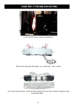
Page 33: ...OOTING Touch the U D sensor module for inspection When you touching the limit switch you should hear click sounds If you can t hear the noise the limit switch module may stuck try to release or replac...

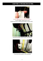
Page 34: ...Mark them before you replace the limit switch The UP DOWN cables should not be installed incorrectly otherwise the machine core will crash And there should be a plastic piece on the left top There sh...

Page 35: ...32 CHAPTER 6 PARTS REPLACEMENT 6 1 Air pump Power on and lift the footrest to the top Footrest on the top position Power switch off disconnect the power cord...

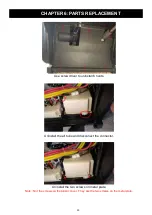
Page 36: ...ACEMENT Use screw driver to uninstall 6 rivets Uninstall the air tube and disconnect the connector Uninstall the two screws on metal plate Note Not the screws on the plastic cover They are the two scr...

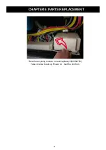
Page 37: ...34 CHAPTER 6 PARTS REPLACEMENT Take the air pump module out and replace 1000392758 Take inverse to set up Power on test the function...

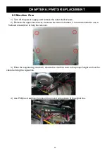
Page 38: ...the upper back cover because the tenon is barbed it is recommended to use a flathead screwdriver to help the removal 3 Enter the engineering mode A0 elevate the machine core to the proper height and c...

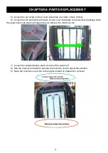
Page 39: ...ews of rear cover side plate to avoid screw breakage when the upper back side plate is propped open to remove the machine core 7 Loosen the supplementary piece screws of the upper rail 8 Use the manua...

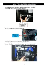
Page 40: ...ist with hands 11 Make the rollers on the upper sides off the rails 12 Utilize the gap of the rear cover side plate 13 Elevate until breaking away from rack engaging state 14 Unplug the power line and...

Page 41: ...btained from the old core 19 After the machine core is installed tighten the rail fixing piece 20 Lock the signal line ground wire on the set screws of the adapter board The picture shows that the gro...

Page 42: ...to the upper limit and confirm that the sensor works normally and adjust the metal plate properly to the center position about 2 mm from both sides 23 Lower the machine core to the lower limit and con...

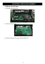
Page 43: ...40 CHAPTER 6 PARTS REPLACEMENT 6 3 Master Control Panel 1 Disconnect all the cable ports 2 Remove the fixing screws 3 Remove the master control panel carefully 1000391515...

Page 44: ...r misc tools 1 Remove the panel underneath the foot rest to do this use the controller to elevate the leg rest up To remove the panel push in the center part of the buttons displayed below this will p...

Page 45: ...down using the controller Once the leg rest is down we need to remove the seat from the massage chair in order to do this we need to pull up on the seat from the back and pull forward There are screw...

Page 46: ...removed with a wrench on the right side and channel lock pliers on the left The left side is connected with a pin that needs to be pulled 5 Once these connections are undone the footrest can be remov...

Page 47: ...s Operation 1 Enter the engineering mode PU refer to 2 5 engineering mode PU to confirm that if the software version needs update 2 While the machine s power is off insert the flash drive with new sof...

Page 48: ...45 CHAPTER 6 PARTS REPLACEMENT 6 6 Machine breakdown drawing...

Page 49: ...47555 Pushrod motor foot 1000394189 Air pipe 1000408290 Air pump 1000392758 Air value 1000392761 Machine core 1000382973 Hand controller 1000405065 PCB board 1000228108 Stopper limit 1000373506 Contro...

Reviews: