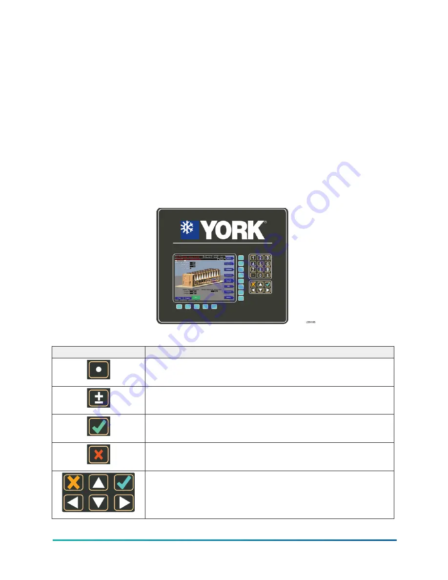
OptiView control center
The YORK OptiView control center LCD graphic display and keypad is the interface for starting,
stopping, configuring, monitoring, and commanding the chiller controls. The control center
is a microprocessor-based system for centrifugal chillers. It controls the leaving chilled liquid
temperature (LCHLT) and maintains safe operation. It is factory-mounted, wired, and tested.
The graphic display presents the operating parameters in logical groups on screens and can
trend data to show a graphical representation of present or historical operation of the chiller. The
locations of various chiller parameters are clearly and intuitively marked. Instructions for specific
operations are provided on many of the screens. For information on the screens and navigation,
OptiView control center functions and navigation
Eight buttons on the right side of the panel are primarily used for navigation between the system
screens. Five additional buttons are located at the base of the display. The button functions are
redefined based on the currently displayed screen. The area to the right of the keypad is used for
data entry and a standard numeric keypad is provided for programming system setpoints and
limits.
Figure 9: OptiView control center
Table 3: OptiView™ control center buttons
Button
Description
The decimal button provides accurate entry of setpoint values.
Use the ± button to enter negative values and select AM/PM during
time entry.
In order to accept changes made to the chiller setpoints, the check
button is provided as a universal Enter button or Accept symbol.
In order to reject entry of a setpoint or dismiss an entry form, the X
button is provided as a universal Cancel symbol.
Cursor arrow buttons are provided to allow movement on screens that
contain a large amount of entry data. In addition, these buttons can be
used to scroll through history and event logs.
17
YVAM Control Center
Summary of Contents for YORK YVAM 0350
Page 2: ...2 YVAM Control Center...
Page 10: ...Figure 4 Variable speed drive nomenclature YVAM Control Center 10...
Page 15: ...Figure 8 System piping and instrumentation diagram P ID 15 YVAM Control Center...
Page 154: ...Figure 62 Sample printout status or history YVAM Control Center 154...
Page 155: ...Figure 63 Sample printout status or history continued 155 YVAM Control Center...
Page 156: ...Figure 64 Sample printout setpoints YVAM Control Center 156...
Page 157: ...Figure 65 Sample printout setpoints continued 157 YVAM Control Center...
Page 158: ...Figure 66 Sample printout schedule YVAM Control Center 158...
Page 159: ...Figure 67 Sample printout sales order 159 YVAM Control Center...
Page 160: ...Figure 68 Sample printout security log report YVAM Control Center 160...


