background image

7

FORM 145.13-NO2 

ISSUE DATE: 1/22/2020

1

Do not run the evaporator fan motor be-

low 30Hz, as coil freeze-up and nuisance 

lockouts may occur. The unit is factory set 

to minimum 30 Hz output with the excep-

tion of the Low Ambient Condenser VFD, 

which is set to 15 Hz. 

The unit does not carry a failsafe circuit 

to bypass the VFD and run the evaporator 

fan in the event of a VFD malfunction.

The unit does not carry a failsafe circuit bypass for the 

evaporator fan in the event of a VFD malfunction. Dur-

ing a VFD failure, the evaporator fan becomes non-

operational. If there is a demand for cooling, the unit 

compressors continue to run until the low pressure 

safety switch trips.

FACTORY SHIPPED

Units that are 8 tons or larger ship with a VFD control-

ler factory installed and wired in the evaporator (air 

handler) corner post. See the dimensional drawings in 

the IOM for the location.

DSV MODELS

The DSV units ship factory split (condenser and evap-

orator) and require assembly in the field. The motor is 

pre-wired to the VFD in the factory. 
To assemble the DSV model in the field:

1.  Plug the low voltage wiring, shipped wired to the 

VFD, to the SE Controller.

2.  Connect the low voltage wires from VFD unit 

(24VDC) to the evaporator fan VFD relay (EVF-

DR). The EVFDR relay acts as a switch to turn on 

the VFD. 

3.  Connect two 1/4 inch Q.C. to common and nor-

mally open positions (red wire to “C,” orange 

wire to “NO”). 

The VFD switch runs on 24VDC. 

Do not cross 24VAC and 24VDC wiring 

on EVFDR relay.

SECTION 1 - INSTALLATION

Do not enter Setup mode when powering 

on the VFD. 
Do not change parameters 4009 and 4011 

for the VAV option on DSH/DSV C-gen 

units. 
For these units, use the Smart Equipment 

(SE) controller to set the VAV setpoint. 

Prior to installing or servicing the unit, 

ensure proper lockout/tagout (LOTO) 

procedures are followed per OSHA 

safety regulations (29 CFR 1910.147 and  

29 CFR 1910.333). Failure to disconnect 

power supply may result in electrical 

shock or even death. 
Always wait for at least 5 minutes after 

disconnecting the power before servicing 

the unit.

BACKGROUND

All D-Series and C-Series units that are 8 tons or larg-

er have a Variable Frequency Drive (VFD) installed. 

There are 2 Controlled Fan Method VFD options: VAV 

differential pressure transducer and discrete speed (3 or 

4 speed) fan control.

Refer to the nomenclature breakdown in 

the appropriate DSV/DSH Installation, 

Operation, and Maintenance (IOM) 

manual and also the nameplate of the unit 

to determine the Controlled Fan Method. 

The tenth digit of the nomenclature (ID 

Motor) identifies which method the unit 

has.
Use the nomenclature to select the low 

ambient condenser option.

For units with the VAV option, the supplied VFD al-

lows the operator to set the external static (0.0–2.5 

"WC), as measured from a supply duct location deter-

mined by field installer and/or as per field specifica-

tions. The VFD controls the frequency (speed) of the 

evaporator fan motor in order to meet the desired exter-

nal static (ESP) setpoint. The VFD controls amps draw 

of the motor and does not allow the motor draw more 

than nominal amps.

Summary of Contents for VFD Series

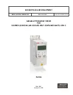
Page 1: ...R 410A VARIABLE FREQUENCY DRIVE FOR D SERIES DSV DSH AIR COOLED SELF CONTAINED UNITS GEN C Issue Date January 22 2020 INDOOR PACKAGED EQUIPMENT INSTALLATION OPERATION NEW RELEASE Form 145 13 NO2 120...

Page 2: ...ent and any referenced materials This in dividual shall also be familiar with and comply with all applicable industry and governmental standards and regulations pertaining to the task in question SAFE...

Page 3: ...whether the equipment has been modified and if current literature is available from the owner of the equipment prior to performing any work on the equipment CHANGE BARS Revisions made to this documen...

Page 4: ...0 HP Motor 237HE 5 0 HP Motor 238HE 7 5 HP Motor 239HE 10 0 HP Motor 1 2 3 4 5 6 7 8 9 10 11 12 13 VFD LAC 234HE 2 A Product Category VFD VFD Program Parameter Set VFD Option LAC Low Ambient Condense...

Page 5: ...lle Cover 10 FIGURE 7 Input Output Diagram 11 FIGURE 8 Evaporator VFD Low Voltage Wiring Schematic With Optional VAV Sensor 208 230 460V 16 FIGURE 9 Evaporator VFD Low Voltage Wiring Schematic 575v 17...

Page 6: ...6 FORM 145 13 NO2 ISSUE DATE 1 22 2020 THIS PAGE INTENTIONALLY LEFT BLANK...

Page 7: ...oss 24VAC and 24VDC wiring on EVFDR relay SECTION 1 INSTALLATION Do not enter Setup mode when powering on the VFD Do not change parameters 4009 and 4011 for the VAV option on DSH DSV C gen units For t...

Page 8: ...units The transducer is supplied with two 1 4 inch OD pres sure fittings and accepts field provided 1 4 inch push on tubing for lengths of up to 300 feet The positive HIGH and negative LOW pressure p...

Page 9: ...ts and the 8 ton DSH unit with 3 refrigeration stages the evaporator fan is set to run at 50 60 and 100 speed The 2 5 ton DSH units and 5 ton DSV unit do not have a VFD as a standard and operate at si...

Page 10: ...e in the supply duct as required run 1 4 inch push on tube to the corner post opening and connect to the positive HIGH side fit ting LD20863 Figure 5 CONNECTING NEGATIVE AND POSITIVE SIDE FITTINGS Che...

Page 11: ...DC for DSH DSV C gen DISPLAY In AUTO MODE the following parameters display on control display 1 30 60Hz is the output frequency to the motor The minimum factory set frequency allowed is 30 Hz 2 0 0 No...

Page 12: ...REF1 MIN 0 Hz 05 REF1 MAX 60 Hz 06 REF2 SELECT AI1 07 REF2 MIN 0 08 REF2 MAX 100 13 ANALOGUE INPUTS 01 MINIMUM AI1 20 02 MAXIMUM AI1 100 14 RELAY OUTPUTS 01 RELAY OUTPUT 1 FLT ALARM 16 SYSTEM CONTROL...

Page 13: ...VE DEPENDENT A 07 MOTOR NOM FREQ 60 Hz 08 MOTOR NOM SPEED DRIVE DEPENDENT rpm 09 MOTOR NOM POWER DRIVE DEPENDENT hp 10 START STOP DIR 01 EXT1 COMMANDS NOT SEL 02 EXT2 COMMANDS DI1 03 DIRECTION FORWARD...

Page 14: ...ACTORY PARAMETERS AND SIGNALS FOR 575V EVAPORATOR SETTINGS ABB ACS250 NAME VALUE UNIT 99 START UP DATA 02 APPLIC MACRO 1 05 MOTOR NOM VOLT DRIVE DEPENDENT V 06 MOTOR NOM CURR DRIVE DEPENDENT A 07 MOTO...

Page 15: ...460 3 60 9 70 VFD LAC 239HE 2 208 230 3 60 10 00 26 00 1770 VFD LAC 239HE 4 460 3 60 12 50 VFD SEC 233HE 2 208 230 3 60 1 00 3 10 1760 VFD SEC 233HE 4 460 3 60 1 50 VFD SEC 233HE 5 575 3 60 1 20 VFD...

Page 16: ...16 FORM 145 13 NO2 ISSUE DATE 1 22 2020 SECTION 2 Operation VFD OPTION SCHEMATICS LD28643 Figure 8 EVAPORATOR VFD LOW VOLTAGE WIRING SCHEMATIC WITH OPTIONAL VAV SENSOR 208 230 460V...

Page 17: ...ION 2 Operation FORM 145 13 NO2 ISSUE DATE 1 22 2020 LD28648 Figure 9 EVAPORATOR VFD LOW VOLTAGE WIRING SCHEMATIC 575V LD28644 Figure 10 EVAPORATOR HIGH VOLTAGE POWER SCHEMATIC FOR ALL UNITS 208 230 4...

Page 18: ...ISSUE DATE 1 22 2020 SECTION 2 Operation LD28647 Figure 11 CONDENSER VFD LOW VOLTAGE WIRING SCHEMATIC 208 230 460V LD28646 Figure 12 CONDENSER VFD HIGH VOLTAGE WIRING SCHEMATIC WITH OPTIONAL MANUAL B...

Page 19: ...19 SECTION 2 Operation FORM 145 13 NO2 ISSUE DATE 1 22 2020 THIS PAGE INTENTIONALLY LEFT BLANK...

Page 20: ...9 www johnsoncontrols com Subject to change without notice Form 145 13 NO2 120 New Release All rights reserved The Smart Equipment logo is a trademark of Johnson Controls in the United States and othe...

Reviews: