


TEC2003-3 Multi-Stage Wireless Thermostat Controller Installation Instructions
10
Enabling Override Schedule
Note:
The Override Schedule prompt only appears
when the thermostat controller is in the unoccupied
state (Unoccupied Mode).
This menu selection gives the user the option of
overriding the unoccupied setpoints with the occupied
setpoints for the amount of time specified under the
TOccTime
parameter. See Table 4.
Note:
If one of the binary inputs is configured to
operate as a remote override contact, this menu is
disabled.
To override the unoccupied state while in the Main User
Menu:
1.
Press the
NO
key to all prompts until the Override
Schedule prompt appears. If the thermostat
controller is in the unoccupied state, this is the first
prompt.
2.
Press the
YES
key to enable the temporary
override. The thermostat controller returns to the
Status Display Menu.
When scrolling through the Status Display Menu,
Override now appears for the schedule status
parameter.
Resuming the Programmed Schedule
This menu only appears when the thermostat controller
is in the override mode.
To resume the schedule while in the Main User Menu:
1.
Press the
NO
key to all prompts until the Resume
Schedule prompt appears. If the thermostat
controller is in the override state, this is the first
prompt.
2.
Press the
YES
key to resume the programmed
schedule.
The thermostat controller returns to the Status Display
Menu.
Entering Permanent Temperature Setpoints
The first prompt appearing in the Main User Menu of
the thermostat controller when in the occupied state is
to set the permanent temperature setpoint. Permanent
setpoints are stored in the programmed schedule.
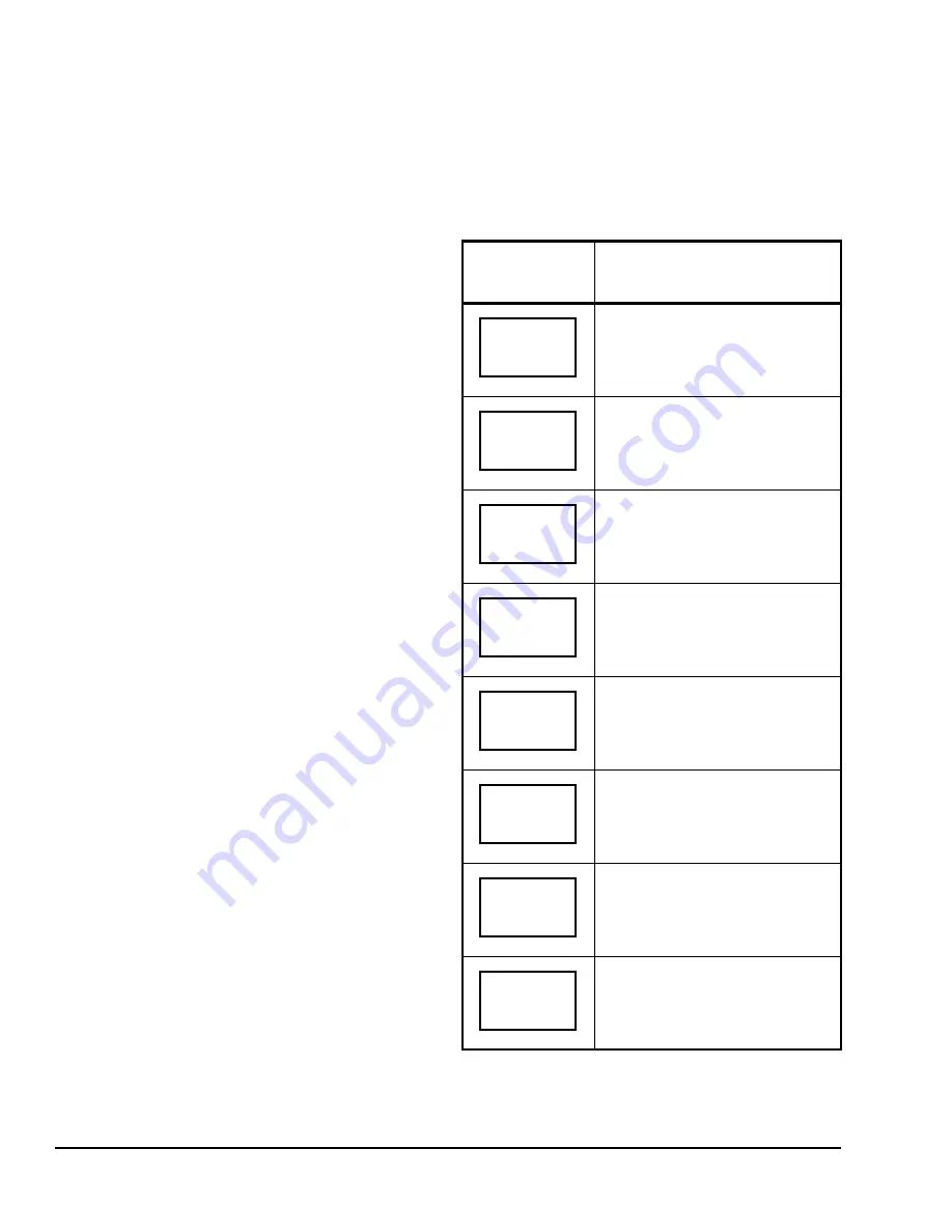
To enter the permanent heating and cooling setpoints
for the Occupied and Unoccupied Modes, follow the
steps in Table 5. When changing the temperatures,
press the keys once to change the temperature in
0.5F°/0.5C° increments; press and hold down the keys
to change the temperature in 5.0C°/5.0F° increments.
Table 5: Entering Permanent Temperature
Setpoints (Part 1 of 2)
Thermostat
Controller
Display
Description
Press the
MENU
key while in the
Status Display Menu to enter the
Main User Menu.
Press the
NO
key to all prompts until
the temperature setpoint prompt
appears on the display (it may be the
first prompt). Press the
YES
key to
enter the temperature setting menu.
Press the
YES
key to change the
occupied cooling setpoint. Press the
NO
key to advance to the occupied
heating setpoint menu.
Press the
UP/DOWN
arrow keys to
set the temperature. Press the
YES
key to store the value and advance to
the next menu.
Press the
YES
key to change the
occupied heating setpoint. Press the
NO
key to advance to the unoccupied
cooling setpoint menu.
Press the
UP/DOWN
arrow keys to
set the temperature. Press the
YES
key to store the value and advance to
the next menu.
Press the
YES
key to change the
unoccupied cooling setpoint. Press
the
NO
key to advance to the
unoccupied heating setpoint.
Press the
UP/DOWN
arrow keys to
set the temperature. Press the
YES
key to store the value and advance to
the next menu.
RoomTemp
75.0
°
F
Temperat
set? Y/N
Cooling
set? Y/N
Cooling
75.0
°
F
Heating
set? Y/N
Heating
68.0
°
F
Unocc CL
set? Y/N
Unocc CL
80.0
°
F