Subject to change without notice. Published in U.S.A.
035-22285-002-B-0914
Copyright
©
2014 by Johnson Controls, Inc. All rights reserved.
Supersedes: 035-22285-002-A-0912
York International Corp.
5005 York Drive
Norman, OK 73069
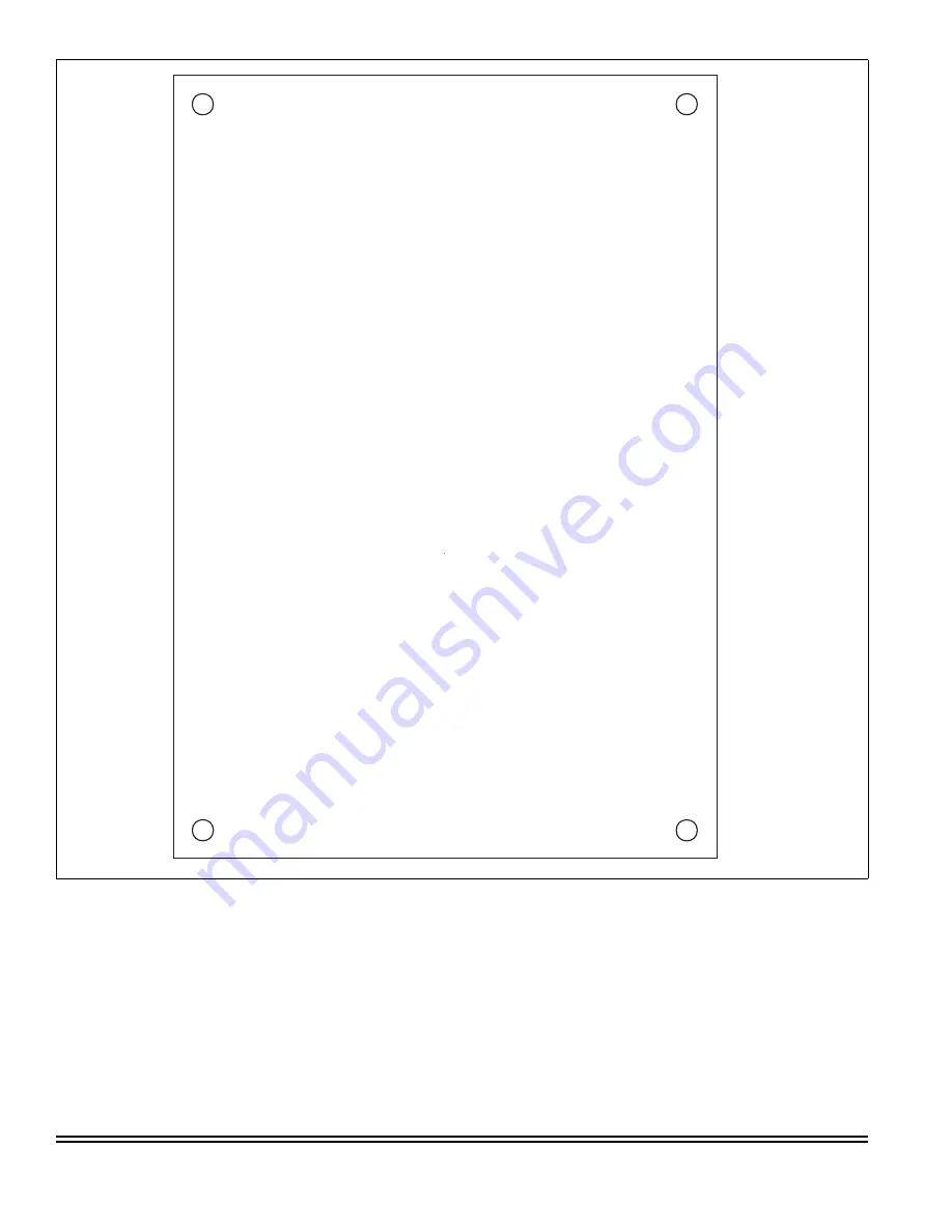
FIGURE 3:
Hole Template
A0235-001


