


34
Network Communications—N2 Communications Bus
•
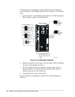
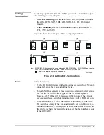
To set the EOL jumpers on the repeater, refer to Table 4 and Figure 15.
Remove the cover of the repeater to get at the EOL jumpers.
Note: Sides A and B have separate EOL settings. Determine the settings
individually.
Table 4: EOL Settings for Repeater
Side
Jumpers
Instructions
Side A
J1 and J2
If at end-of-line, install both jumpers over Pins 1 and 2
(EOL In).
If not at end-of-line, install both jumpers over Pins 2 and 3
(EOL Out).
If not at end-of-line and repeater is only switch-terminating
device on segment, install both jumpers over Pins 1 and 2
(EOL In).
Side B
J3 and J4
If at end-of-line, install both jumpers over Pins 1 and 2
(EOL In).
If not at end-of-line, install both jumpers over Pins 2 and 3
(EOL Out).
If not at end-of-line and repeater is only switch-terminating
device on segment, install both jumpers over Pins 1 and 2
(EOL In).
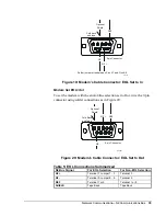
The 2110 modem does not have an EOL jumper to set. The EOL selection
is instead accomplished by properly terminating the N2 wires to the 9-pin
connector. Soldering the wires to specific pins and soldering two jumper
wires configures the modem as an end-of-line device. (For a summary,
refer to Table 5.)
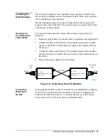
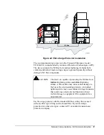
Modem Set EOL=In
To set the modem as an end-of-line device, wire the 9-pin connector using
solder connections as shown in Figure 19.
Setting
Termination on
Fiber Modems


