Johnson Controls M9220-GG-3 Series Installation Manual Download Page 5

M9220-GGx-3 Proportional Electric Spring Return Actuators Installation Guide

5

Counterclockwise (CCW) Spring Return 
Direction – Clockwise (CW) Powered 
Operation

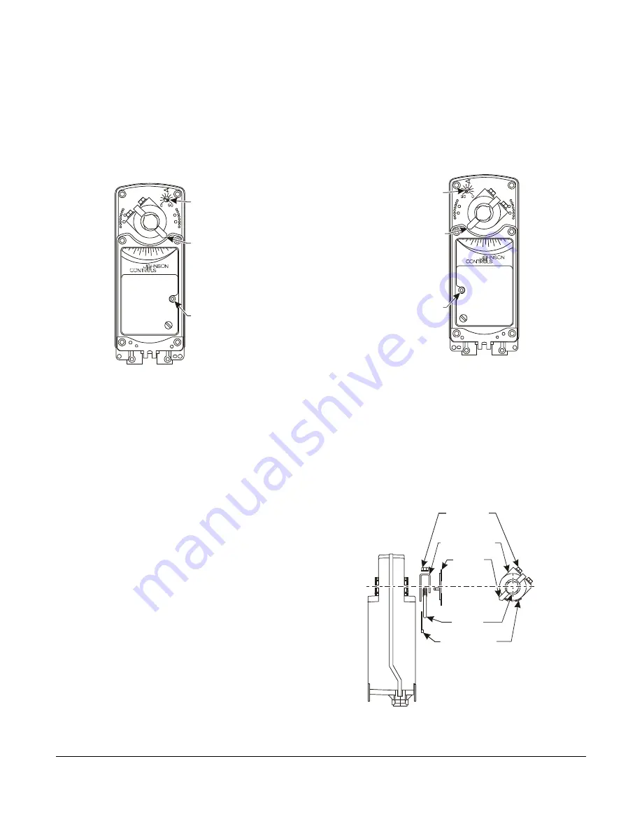
For CCW spring return direction, mount the actuator to 
the damper shaft so that Side A of the actuator is away 
from the damper as illustrated in Figure 2. With power 
applied, the actuator drives CW from the 0° position, 
and spring returns CCW. 

Clockwise (CW) Spring Return Direction – 
Counterclockwise (CCW) Powered Operation

To change the spring return direction to CW, mount the 
actuator to the damper shaft so that Side B of the 
actuator is away from the damper as illustrated in 
Figure 3. With power applied, the actuator now drives 
CCW from the 0° position, and spring returns CW. 

Removable Coupler

The coupler may be installed on either side of the 
output hub. If the damper shaft is less than 3-19/32 in. 
(91 mm) long, insert the coupler in the face of the 
actuator closest to the damper. If the damper shaft is 
shorter than 1-5/32 in. (29 mm) long, a shaft extension 
is required to mount the actuator.

Figure 2:  Side A of Actuator

A

90

-5

10

20

30

40

50

60

70

80

Manual
Override

Pointer Showing
Actuator in the
Spring Return
Position

Auxiliary Switch
Adjuster Located 
on the Right

FI

G

:s

id

ea

Side A: CCW Spring Return Direction

Figure 3:  Side B of Actuator

B

90

-5

10

20

30

40

50

60

70

80

Auxiliary Switch

Adjuster Located 

on the Left

Pointer Showing

Actuator in the

Spring Return

Position

Manual

Override

FI

G

:s

id

eb

Side B: CW Spring Return Direction

Figure 4:  Changing the Position of the Coupler

Shaft Coupler

U-Bolt Nut

and Washer

(Qty Two)

Pointer

U-Bolt 

Locking Clip

FIG

:ch

pos

Assembled View

 of Coupler

 Subassembly

Summary of Contents for M9220-GG-3 Series

Page 1: ... only to control equipment under normal operating conditions Where failure or malfunction of the electric actuator could lead to personal injury or property damage to the controlled equipment or other property additional precautions must be designed into the control system Incorporate and maintain other devices such as supervisory or alarm systems or safety or limit controls intended to warn of or...

Page 2: ...s the electrical connections and wiring details are also included on the actuator housing Parts Included Proportional electric spring return actuator with coupler Anti rotation bracket Manual override crank Two M3 x 9 5 mm self drilling sheet metal mounting screws Two No 10 32 x 9 16 in thread forming conduit screws Special Tools Needed Torque wrench with 3 8 in 10 mm socket Digital voltmeter Flat...

Page 3: ...ions Figure 1 M9220 GGx 3 Proportional Electric Spring Return Actuator Dimensions in mm A 4 102 10 5 16 262 2 3 16 56 FIG M9210_9220_dimen 1 3 4 44 1 8 3 3 3 16 81 3 4 19 2 3 16 56 1 25 2 51 1 19 32 40 1 1 16 27 1 4 6 5 Mounting Hole 6 Locations 1 19 32 40 1 19 32 40 6 15 16 176 10 254 ...

Page 4: ...ity 1 M9000 320 Weather Shield Enclosure NEMA 3R enclosure for protecting a single M9210 20 actuator from rain sleet or snow quantity 1 M9000 400 Jackshaft Linkage Kit Open ended design enables clamping onto a jackshaft without requiring access to the ends of the jackshaft quantity 1 M9000 519 Valve linkage for mounting M9220 actuator to 2 1 2 to 6 in flanged ball valves M9000 604 Replacement Anti...

Page 5: ...W Removable Coupler The coupler may be installed on either side of the output hub If the damper shaft is less than 3 19 32 in 91 mm long insert the coupler in the face of the actuator closest to the damper If the damper shaft is shorter than 1 5 32 in 29 mm long a shaft extension is required to mount the actuator Figure 2 Side A of Actuator A 90 5 10 20 30 40 50 60 70 80 Manual Override Pointer Sh...

Page 6: ...e direction to lock the actuator hub in place Note To unlock the actuator hub rotate the manual override crank in the direction indicated by the arrow on the label The actuator hub automatically unlocks when power is applied to the actuator and returns the actuator to normal drive and spring return operation Mounting the Actuator To mount the actuator proceed as follows 1 See the dimensions in Fig...

Page 7: ...n unused mounting hole 10 Apply power long enough for the actuator to travel a full stroke and verify that the actuator rotates freely throughout the range Note If electric power is not available complete this verification by reinserting the manual override crank and turning it in the direction indicated to rotate the coupler to the fully open position Rotation Range Using Optional M9220 603 Adjus...

Page 8: ...tween 5 to 90 causes the output hub to stop motion and hold its position until power is removed Rotation is mechanically limited to the 5 and 90 positions by integral end stops Optional end stops are available to limit the output hub travel An anti rotation bracket prevents rotational movement of the actuator body See Figure 9 Figure 10 and Figure 11 for proper wiring of the M9220 GGx 3 Proportion...

Page 9: ... V Figure 11 M9220 GGx 3 Control Wiring Diagram Overrides 1 2 3 4 Y COM U BLK RED GRY ORN Override to MIN position AC 24 V DC 0 2 10 V DC 0 2 10 V A A Open MIN Position A Closed Normal Operation 1 2 3 4 Y COM U BLK RED GRY ORN Override to MAX position AC 24 V DC 0 2 10 V DC 0 2 10 V C B Closed MAX Position C Closed Normal Operation B 1 2 3 4 COM U BLK RED GRY ORN Override to MIN MID MAX positions ...

Page 10: ...ion range The actuator stores the reduced rotation range in nonvolatile memory retains data when power is lost or removed To calibrate the control input range proceed as follows 1 With power off move the mode selection switch to the CAL position Figure 13 Then energize the actuator The actuator automatically rotates until the end stops are found and proportionally reconfigures the control input ra...

Page 11: ...nning Power x 1 5 Only one of the actuators can be configured as the master Set the selector switch to the master position Figure 15 The other GGx actuator s must be configured as subordinate s by setting the tandem selector switch to the subordinate position The master can accept DC 0 10 V or DC 2 10 V or 4 20 mA command signals based on the master s switch settings and or external resistor The m...

Page 12: ...liary Switch No 1 is 11 closing and the nominal factory setting for Auxiliary Switch No 2 is 81 opening relative to a 0 to 90 rotation range See the Technical Specifications table for the auxiliary switch ratings The switch point of Auxiliary Switch No 1 is fixed The switch point of Auxiliary Switch No 2 is independently and continuously adjustable from 25 to 95 See Figure 17 and use the method in...

Page 13: ...lly open position and holds while power is applied 4 Observe the switch point If required repeat Steps 2 and 3 Repairs and Replacement A number of replacement parts are available see Table 1 for more details If the M9220 GGx 3 Proportional Electric Spring Return Actuator fails to operate within its specifications replace the unit For a replacement electric actuator contact the nearest Johnson Cont...

Page 14: ...ction is selectable with mounting position of actuator Side A actuator face away from damper for CCW spring return Side B actuator face away from damper for CW spring return Running and Spring Return Torque 177 lb in 20 N m for a single actuator 354 lb in 40 N m for two like models mounted in tandem 531 lb in 60 N m for three like models mounted in tandem Rotation Range Adjustable from 30 to 90 CW...

Page 15: ...isted CCN XAPX7 File E27734 to CAN CSA E60730 1 Automatic Controls for Household and Similar Use and CAN CSA E60730 2 14 Part 2 Particular Requirements for Electric Actuators Models All Europe CE Mark Johnson Controls declares that this product is in compliance with the essential requirements and other relevant provisions of the EMC Directive and Low Voltage Directive Australia and New Zealand RCM...

Page 16: ... johnsoncon Technical support Region Group Contact information North America Product Technical Support 1 800 275 5676 Option 2 Product Technical Support then Option 1 HVAC psotechsupport jci com Option 2 FX and Metasys Option 3 PENN Controls Refrigeration refrig techsupport jci com Field Support Center CGFieldSupportCenter jci com 1 800 524 1330 Applied DX Technical Support applieddxtechsupport jc...

Reviews: