M9000-310 and M9000-320 Series Weather Shield Enclosures Installation Instructions
6
8.
Install the two conduit fittings included with the kit
into the enclosure base and secure them in place
using the threaded hex nuts.
Steps 9 and 11 apply only to the M9000-320 kit when
used with the M9220 Series actuators. For the M9000-
310 kit, proceed to Step 12.
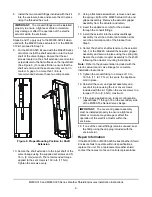
9.
For the M9000-320 kit used with the M9220 Series
actuators, install the shaft extension onto the input
shaft of the valve linkage. Ensure that the set
screws located on the shaft extension are oriented
perpendicular to the flat surfaces on the input shaft.
(See Figure 6.) To reduce friction, ensure that the
shaft extension and the seal assembly are not in
contact. A gap of no more than 1/8 in. is
recommended between these two components.
10. Secure the shaft extension to the input shaft of the
valve linkage using the supplied set screws and 5/
16 in. (8 mm) wrench. The recommended torque
applied to the set screws is 100 in·lb (11 N·m).
Tighten the screws evenly.
11. Using a flat blade screwdriver, remove and save
the spring clip from the M9220 actuator hub and
gripper assembly. Remove the actuator gripper
assembly from the actuator and retain.
12. Insert the appliance cord(s) for the actuator
through the conduit fittings.
13. Install the actuator into the enclosure/linkage
assembly. Insert the actuator anti-rotation slots
over the anti-rotation tab of the bracket from
Step 3.
14. Center the shaft or shaft extension in the actuator
hub. For the M9220, reinstall the actuator gripper
assembly and secure in place using the spring clip.
Secure the actuator coupler assembly to the shaft
following the actuator mounting instructions.
Note:
Refer to the documentation included with the
electric actuator and valve linkage for complete
installation instructions.
15. Tighten the conduit fitting to a torque of 10 to
15 lb·in (1.1 to 1.7 N·m) to secure the appliance
cord in place.
16. Reinstall the cover and gasket assembly and
secure it in place using the four cover screws
included with the kit. Tighten the cover screws to a
torque of 5 lb·in (0.6 N·m) maximum.
17. If the valve application is a tandem configuration,
repeat Steps 11 through 16 on the secondary side
of the M9000-53x Series Valve Linkage.
18. If one of the conduit fittings remains unused, seal
the fitting using the cap plug included with the
enclosure kit.
Repair Information
If the M9000-310 or M9000-320 Series Weather Shield
Enclosure fails to operate within its specifications,
replace the unit. For a replacement weather shield,
contact the nearest Johnson Controls representative.
IMPORTANT:
The conduit fittings must be installed
properly to ensure a tight seal. Water or moisture
may damage or affect the operation of the electric
actuator within the enclosure.
Figure 6: Proper Mounting Position for Shaft
Extension
F
IG
:m
n
tg
_
p
o
s
IMPORTANT:
The cover and gasket assembly
must be installed properly to ensure a tight seal.
Water or moisture may damage or affect the
operation of the electric actuator within the
enclosure.


