NCB-IM Component Descriptions
NCB-IM Routers
27
IFI Routers/Repeaters Installation & Operation Manual - P/N: 53388:Rev: A1 5/5/09
4.3 NCB-IM Component Descriptions
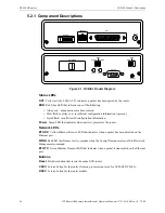
Figure 4.2 NCB Series Front Panel
LED Descriptions
Each NCB-IM router has five LEDs that provide network and modem diagnostic information.
These LEDs function as follows:
ACT (yellow)
Indicates a packet has been passed by the router.
ERR
Red error color indicates one of three things:
• Always on: a diagnostic error has occurred.
• Slow flash or always on: insufficient configuration information is present.
• Quick flash: insufficient IP configuration information.
Power
Green color indicates when power is present for the router.
• Flashes if DC input to module is below minimum required voltage.
• Flashes for two seconds if a Wink network message is sent to the network processor.
4.4 NCB-IM Installation
4.4.1 NCB-IM Requirements
To use a NCB-IM the following components are required:
•
•
Telephone wire media with RJ11 termination.
•
JNISCAB-5 enclosure (ordered separately).
•
HSP-121 Power Line Surge Suppressor (required and included with JNISCAB-5 order).
•
DITEK 2MLPL110B or EDCO PC2TEL line protectors (not included).
NCB-IM Components
These are the main components that are shipped with a NCB-EL order:
•
NCB-IM Network Combiner Module.
•
FTXC Echelon SMX network transceiver (installed).
•
NCB transformer power supply (+24 VDC 400mA, center POSITIVE, outer NEGATIVE).
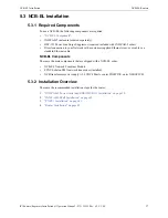
4.4.2 Installation Overview
This is the recommended installation order for a NCB-IM:
•
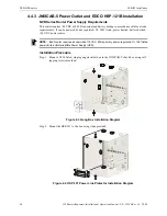
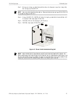
“JNISCAB-5 Power Outlet and EDCO HSP-121B Installation” on page 28
.
•
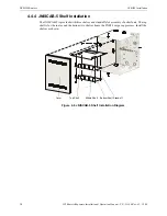
“JNISCAB-5 Shelf Installation” on page 30
•
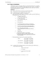
“Router Installation” on page 31
ON 1 2 3 4 5 6 7 8
CMD CSVC RSVC OPTION A
AUDIO CD OH LINE
DC IN
NETWORK
NCB NETWORK COMBINER
ERR
PWR ACT
RESET
Echelon Network Connector
Optional Handset Connector
Modem Line LEDs
Modem
Line RJ-11
Connector
Configuration DIP Switches
Service Pins
Transformer Power Connector
Network LEDs
Hardware Reset
Pin for NCB Router


