
Mounting the camera to a surface (continued)
13. Use a screwdriver to remove the safety wire screw (2) (Figure 9) on the
camera.
14. Insert the safety wire screw into the
‘loop’ at the end of the safety wire (1)
(Figure 9) and then insert the screw back into the hole on the camera.
15. Use a screwdriver to securely attach the screw into the camera.
Figure 9
16. Hold the camera up to the flat bracket and insert the three screws on the
camera (7) (Figure 3) up into the three holes in the flat backet and then rotate
the camera clockwise until it clicks into place on the flat bracket.
Note:
T
he ‘RED’ dots on the camera and flat bracket must align up correctly.
Note:
Rotate the camera counterclockwise to remove it from the flat bracket.
17. Use the torx wrench to rotate the security screw (1) (Figure 10)
counterclockwise to securely attach the camera to the flat bracket.
Security
Table 2: Camera buttons and connections descriptions
No
Name
Description
1
Reset &
Default button
Press for less than 1 second to reboot the camera;
pressing for 6 seconds to restore the camera to the
factory default settings.
Micro SD Card
Slot
Insert a micro SDHC / SDXC card (customer supplied)
into the slot for recording and file storage.
2
RJ-45 PoE
Port
Pre-fitted RJ-45 cable connection slot
24 V AC
Power Ports
To power on the camera, connect a 24 VAC power
source to the corresponding 2-pin ports.
3
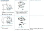
DI/DO
Terminal Ports
Connect to several external devices for audio and alarm
input / output functions, which can expand the usability
of the camera for a variety of field applications. See
Figure 5 for details on port definitions.
Figure 5: I/O port descriptions
Figure 5
Figure 5: I/O port descriptions (continued)
Note:
The power supply terminal / adaptor for IO connectors and field wiring should
comply with the Class 2 circuit standard to ensure safety from electrical fires and
providing acceptable against electrical shock. The alarm out pin is a 30 VDC output
signal with a maximum load of 1 A. The alarm in pin acts as a switch, which is either
NO (Normal Open) or NC (Normal Closed).
Mounting the camera to a surface
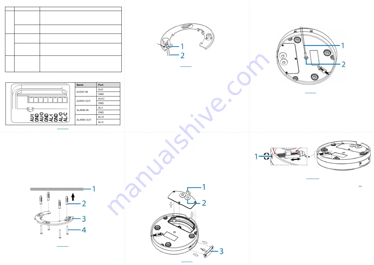
1.
Place the mounting template sticker onto the surface.
2.
On the surface (1) (Figure 6) drill four Ø 6mm holes and insert the four
plastic screw anchors (2) (Figure 6) into the four Ø 6mm holes.
3.
Hold the flat bracket (3) (Figure 6) up to the surface and align the four holes
on the flat bracket with the four holes on the surface.
Figure 6
Mounting the camera to a surface (continued)
4.
Insert the four screws (4) (Figure 6) into the four screw anchors and use
the screwdriver to securely attach the flat bracket to the surface.
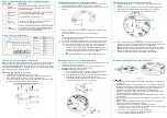
5.
Insert the safety wire (2) (Figure 7
) onto the ‘hook’ (1) (Figure 7) on the flat
bracket.
Figure 7
6.
Use the screwdriver to remove the three screws on the camera rear cap
cover (12) (Figure 3).
7.
Connect the 24V AC cable to the 2-pin port on the camera.
OR
Connect the RJ-45 jack to a PoE compatible network device that supplies
power through the ethernet cable.
8.
Connect the audio and alarm cables to the 8-pin terminal. (See Figure 5).
9.
You can route all cables through the two waterproof rubber holes on the
rear cap (11) (Figure 3)
or
through the cable side entry cap (6) (Figure 2).
a. Remove the rubber plug (1) (Figure 8) and the two waterproof
rubber inserts (2) (Figure 8) and then thread all cables through the
waterproof rubber inserts. Ensure that the waterproof rubber inserts
are inserted correctly back into the holes on the camera.
OR
a. Route all cables through the cable side entry slot (6) (Figure 3).
Mounting the camera to a surface (continued)
10. Hold the rear cap up to the camera and align the three holes on the rear cap
with the three holes on the camera.
11. Insert the three screws into the three holes and use a screwdriver to
securely attach the rear cap cover to the camera.
12.
OPTIONAL:
Inserting a micro-SD card.
a. Use the screwdriver to remove the two screws on the SD card slot
cover (3) (Figure 8) and then insert a micro-SD card.
b. Hold the SD card slot cover back up to the camera and align the two
holes on the cover with the two holes on the camera.
c. Insert the two screws into the two holes and use a screwdriver to
securely attach the SD card cover to the camera.
Figure 8
Mounting the camera to a surface (continued)
Figure 10
WARNINGS
•
This camera operates at: IEEE 802.3af Class 3, PoE 48V DC / 11.89W
or
24V
AC / 11.77W.
•
Installation and service should be performed only by qualified and experienced
technicians and comply with all local codes and rules to maintain your warranty.
•
We are NOT liable of any damage arising either directly or indirectly from
inappropriate installation which is not depicted within this document.
•
Wipe the camera with a dry soft cloth. For tough stains, slightly apply diluted
neutral detergent and wipe with a dry soft cloth.
•
Do not apply benzene or thinner to the camera, which may cause the surface to
melt or lens fog.
•
Avoid aligning the lens with extremely bright objects (e.g., light fixtures) for long
periods of time.
•
Although this camera is waterproof and suitable for both indoor and outdoor
usages, do not immerse the camera into water.
•
Avoid operating or storing the camera in the following locations:
•
Extremely humid, dusty, or hot/cold environments (recommended operating
temperature: -40°F to +122°F/-40°C to +50°C).
•
Close to sources of powerful radio or TV transmitters.
•
Close to fluorescent lamps or objects with reflections.
•
Under unstable or flickering light sources.


