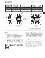
LD14010
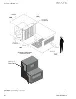
SHEAVE
CENTER
LINES
BELT CENTER
LINES
A
A
FIGURE 12 -
SHEAVE ALIGNMENT
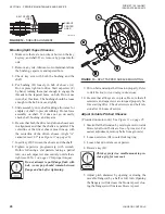
Mounting Split Tapper Sheaves
1. Make sure there are no nicks or burrs on the key,
keyway, and shaft. If so, remove by proper meth-
ods.
2. Remove any oils, lubricants or contaminants from
the bushing, capscrew, and tapered bore.
3. Check key size with both the bushing and the
shaft.
4. Put bushing (B) loosely in hub of sheave (A).
Do not press tight onto drive. Start capscrew (C)
by hand, turning them just enough to engage the
threads in the tapered holes on hub. Do not use
wrench at this time. The bushing should be loose
enough in the hub to move slightly.
5. Slide assembly on to shaft making allowance for
endplay of shaft to prevent rubbing. Do not force
assembly on shaft. If it does not go on easily,
check shaft, bushing, and key size.
6. Be sure that both the driver and driven sheaves are
in alignment and that the shafts are parallel. The
centerline of the driver sheave must line up with
the centerline of the driven sheave. Angle “A”
7. Insert key (D) between the sheave and the shaft.
8. Tighten capscrews progressively with wrench.
Dothis following a star pattern, taking a partial
turn on each capscrew successively until all are
for proper torque).
Do not attempt to pull flange flush with
hub - some gap should remain between
flange and hub after tightening.
FIGURE 13 -
SPLIT TAPPER SHEAVE MOUNTING
9. Put on belt and adjust belt tension properly.
Refer
to Belt Section for tensioning instructions.
10. Be sure that all keys are in place. Be sure that all
setscrews and capscrews are torqued properly be-
fore starting drive. Check setscrews and belt ten-
sion after 24 hours of service.
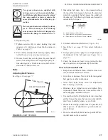
Adjust Variable Pitched Sheaves
(Provided on motor only). See
1. Slack off all belt tension by moving motor towards
blower shaft until belts are free of groove(s). For
easiest adjustment, remove belts from groove(s).
2. Loosen setscrew (B) in outer locking ring.
3. Loosen but do not remove capscrew.
4. Remove key (D).
This key projects a small amount to pro-
vide a grip for removal.
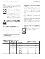
5. Adjust pitch diameter by opening or closing the
movable flange(s) by a half or full turn. Opening
the flange(s) will decrease the blower speed, clos
-
ing the flange(s) will increase blower speed.
JOHNSON CONTROLS
26
FORM ET102.19-NOM1
ISSUE DATE:08/26/2013
SECTION 4 - PERIODIC MANINTENANCE AND SERVICE

