


E-Link Gateway Installation Instructions
3
Mounting
OptiView Panel Installation
1.
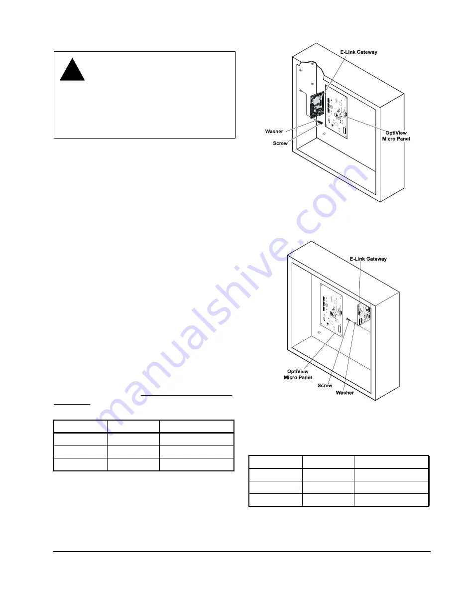
Attach the E-Link Gateway board to the studs
provided inside the chiller enclosure (Figure 1 or
Figure 2), using the four screws and washers
provided in the OptiView/Latitude installation kit.
2.
Connect the communications cable (included with
the kit) from Port 2B on the E-Link Gateway to J2
on the OptiView Micro Panel. Ensure that wires are
connected according to Table 3.
3.
Check for stray wire strands, which could cause
short circuits, and ensure all components are
secure.
4.
Connect the BAS network to Port 1 (if the protocols
are transported by RS-485) or Port 4 (if the BAS
network is L
ON
W
ORKS
).
Note:
For RS-485 2-wire operation, connect a 100
ohm 1 W resistor between COM and the E-Link
Gateway’s TB5 COM (see Figure 24).
5.
Ensure jumper JP27 is set for RS-232 (see
Figure 20).
6.
Connect the power harness (included with the kit)
from J2 on the E-Link Gateway to J21 on the
Optiview Micro Panel (see Figure 20).
The E-Link Gateway is now ready to be configured
using Quick Start; see the
section in this document.
!
WARNING: Risk of Electric Shock.
Disconnect or isolate all power supplies
before making electrical connections.
More than one disconnect or isolation
may be required to completely de-
energize equipment. Contact with
components carrying hazardous voltage
can cause electric shock and may result
in severe personal injury or death.
Table 3: OptiView Wiring - E-Link Port 2B
E-Link Port 2B
OptiView Port
Wire Color
RX
GTX
Black
TX
GRX
Red
REF
N/A
Shield/Drain
Table 4: BAS Wiring - E-Link Port 1
E-Link Port 1
BAS
Wire Color
+
+
White
-
-
Blue
REF
REF
Black
FI
G
:Op
ti
_
P
n
l
Figure 1: OptiView Micro Panel Connected to
E-Link Gateway
FI
G:
Op
ti
_
P
nl
1
Figure 2: OptiView Micro Panel for YMC
2
Connected to E-Link Gateway


