background image

MODEL DSH024C–120C

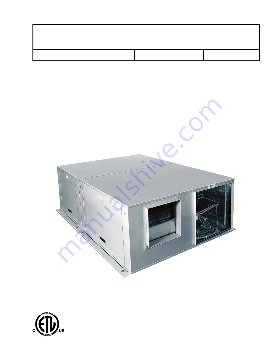
HORIZONTAL R-410A AIR CONDITIONING UNITS

C GENERATION

SMART EQUIPMENT CONTROLLER

Issue Date:  

April 8, 2019

AIR-COOLED SELF-CONTAINED UNITS

INSTALLATION, OPERATION, MAINTENANCE

Supersedes: 145.32-IOM5 (818) Form 145.32-IOM5 (419)

LD2897

Summary of Contents for DSH024C Series

Page 1: ...IZONTAL R 410A AIR CONDITIONING UNITS C GENERATION SMART EQUIPMENT CONTROLLER Issue Date April 8 2019 AIR COOLED SELF CONTAINED UNITS INSTALLATION OPERATION MAINTENANCE Supersedes 145 32 IOM5 818 Form 145 32 IOM5 419 LD2897 ...

Page 2: ... with all applicable industry and governmental standards and regulations pertaining to the task in question SAFETY SYMBOLS The following symbols are used in this document to alert the reader to specific situations Indicates a possible hazardous situation which will result in death or serious injury if proper care is not taken Indicates a potentially hazardous situa tion which will result in possib...

Page 3: ...n formation and any other changes in spelling grammar or formatting are not included MANUAL DESCRIPTION FORM NUMBER Mobile Access Portal Gateway Product Bulletin LIT 12011884 Airside Economizer Kit for Models DSH DSV Air Cooled Air Conditioning Units C Generation Installation and Operation Instructions 145 10 NO2 Low Ambient Damper Kit for Air Cooled Self Contained Units DSH DSV Models B C Styles ...

Page 4: ...w Ambient Control VFD INDOOR AIRSIDE OPTIONS A Standard AirsideCoil C Corrosion Protective Coating D Stainless Steel Drain Pan F Coated Coil with Stainless Steel Drain Pan HEATING OPTIONS 0 None INDOOR FAN OPTIONS 1 Standard 2 High Static 3 Standard with VFD VAV 4 High Static with VFD VAV 5 Standard with VFD Discrete Speeds 6 High Static with VFD Discrete Speeds Evaporator and condenser motor VFD ...

Page 5: ...rvice Clearances 20 Unit Corner Weights 22 Ductwork 23 Louver Sizing Guidelines 23 Electrical Wiring 23 Packaged Unit 24 Split System 24 Low Voltage Wiring 24 Typical Wiring Schematics 24 Fan Performance 28 Motor and Pulley Data 32 Blower Speed Adjustment 34 Adjusting the Blower Speed 34 Low Ambient Damper 34 Airside Economizer ASE 36 Sequences of Operation 36 Air Temperature Sensors 37 Variable F...

Page 6: ...CD Display 41 Safety Monitoring 41 Low Ambient 41 Anti Short Cycle Delay ASCD Protection 41 Fan Delays 41 Nuisance Trip Protection and Three Strikes 41 Lead Lag 41 Condensate Overflow Switch 42 Operation 42 SECTION 3 MAINTENANCE AND SERVICE 43 Evaporator and Condenser Coils 43 Refrigerant Circuits 43 Blowers 43 Drive Belts 43 Filters 43 APPENDIX WIRING DIAGRAMS 45 R 410A QUICK REFERENCE GUIDE 51 ...

Page 7: ...4 060C Low Voltage Wiring Diagrams 47 FIGURE 24 DSH0120C Low Voltage Wiring Diagrams 48 FIGURE 25 Typical Airside Economizer Wiring Diagram 50 LIST OF FIGURES LIST OF TABLES TABLE 1 Operating Weight 11 TABLE 2 Field Split Coupling Kits 12 TABLE 3 Recommended Refrigerant Line Sizes 15 TABLE 4 Electrical Data Standard Evaporator Motor 27 TABLE 5 Electrical Data Oversized Evaporator Motor 27 TABLE 6 ...

Page 8: ...8 FORM 145 32 IOM5 ISSUE DATE 04 08 2019 THIS PAGE INTENTIONALLY LEFT BLANK ...

Page 9: ...which is needed to maintain a proper refrigerant head pressure Only qualified personnel should perform installation and service of this equipment PRE INSTALLATION INSPECTION OF EQUIPMENT All units are factory tested to ensure safe operation and quality assembly The units are packaged and sealed on shipping skids and ship in first class condition Re port to the carrier any torn or broken packaging ...

Page 10: ...e options P Applies to only 2 8 ton models The unit comes assembled as a packaged unit and factory charged with R 410A refrigerant P is ideal for installations where the unit is in stalled as a packaged system While moving the equipment into position or during installation no separation is required S The unit is factory split and factory charged with R 410A refrigerant The unit comes with refrig e...

Page 11: ...rapping of the evaporator condensate drain See Typical Service Clearances on page 20 for more unit clearance information SEPARATION OF THE UNITS All models can be ordered with refrigerant shut off valves or couplings These components allow the evaporator and condenser sections to ship factory split The evaporator and condenser can then be assembled onsite without re quiring the entire unit refrige...

Page 12: ... condensing section of the unit This allows the best access for reconnection or attachment of an extended line set in the case of a split system 5 Remove the interconnecting wiring between the evaporator and condenser electrical panel Dis connect the wire terminations in the condenser electrical panel and pull the excess wire into the evaporator panel 6 Remove the threaded wire bushing connecting ...

Page 13: ...STALLATION CONFIGURATION Horizontal Ductable Ceiling Air Conditioner Packaged Installation Horizontal Ductable Ceiling Air Conditioner Split Installation Condenser Section Top Joining Strip Evaporator Section Side Cross Member Angle Ceiling Exhaust Outdoor Air Intake Condenser Section Evaporator Section Supply Return ...

Page 14: ...TION CONFIGURATION Ductable Ceiling Air Conditioner Split Installation Horizontal Horizontal Ductable Ceiling Air Conditioner Packaged Installation Condenser Section Evaporator Section Supply Air Return Air Outdoor Air Intake Exhaust Ceiling Floor Condenser Section Evaporator Section Ceiling Floor Return Air Supply Air ...

Page 15: ...e same elevation the refrigerant line sizes usually can be matched with factory supplied fittings See Table 3 There are exceptions for total line lengths exceeding 75 feet where pressure drop limitations are exceeded For further information refer to General Piping Recommendations and Refrigerant Line Length Form 247077 UAD H 0209 The following guidelines apply to field fabricated piping Use hard d...

Page 16: ...x Access Low Voltage Connection Electrical Power Connection Front Evaporator Fan Access Condenser Fan Access Condenser Openings Evaporator Fan Access Condenser Fan Access Back Evaporator Openings 0 75 inch NPT Drain Connection Optional Condenser Intake Field Convertible Evaporator Section Condenser Section Optional Return Air Field Convertible Front 4 75 26 00 16 00 7 75 17 50 7 00 1 00 23 75 2 38...

Page 17: ...ge Connection Electrical Power Connection Front Evaporator Fan Access Condenser Fan Access Condenser Openings Evaporator Fan Access Condenser Fan Access Back Evaporator Openings 0 75 inch NPT Drain Connection Optional Condenser Intake Field Convertible Evaporator Section Condenser Section Optional Return Air Field Convertible Front 16 00 8 13 4 75 28 00 18 50 8 75 17 50 10 12 1 00 26 75 2 38 23 13...

Page 18: ...C 2 94 82 50 33 38 30 13 29 38 10 88 10 88 10 88 2 25 20 94 2 63 Evaporator Section Condenser Section Evaporator Section Condenser Section 112 00 39 88 Evaporator Opening Compressor Access Panel Condenser Blower Drive Access Panel Compressor Section Electrical Box Access Evaporator Section Electrical Box Access Evaporator Blower Drive Access Panel Condenser Opening Filter Access Both Sides TX Valv...

Page 19: ...0 10 1 4 70 Evaporator Section Electrical Box Access Front View Right View Back View Left View Top View Evaporator Blower Drive Access Panel Condenser Discharge Condenser Blower Drive Access Panel Condenser Access Panel Service Hose Access Compressor Section Electrical Box Access TX Valve and Filter Drier Access Panel Power Connection Evaporator Discharge Evaporator Intake Sight Glass View Access ...

Page 20: ...701 Figure 10 2 5 TON HORIZONTAL A C UNIT SERVICE CLEARANCES Front Return Air Supply Air Evaporator Section Condenser Section Condenser Intake Condenser Discharge 36 Inch Minimum Clearance 36 Inch Minimum Clearance Evaporator Fan Access Condenser Fan Access 4 Inch Minimum Clearance for Drain Trap ...

Page 21: ... 11 8 AND 10 TON HORIZONTAL A C UNIT SERVICE CLEARANCES Back View Top View 36 Inch Minimum Clearance Evaporator Section Condenser Section Evaporator Section Condenser Section Top View Return Air Supply Air 36 Inch Minimum Clearance 36 Inch Minimum Clearance 4 Inch Minimum Clearance for Drain Tap Condenser Intake ...

Page 22: ...7703 Figure 12 PACKAGED UNIT INSTALLATION UNIT POINT WEIGHTS LBS TOTAL 1 2 3 4 5 6 7 8 OPERATING SHIPPING 2 Ton 138 76 66 112 75 70 72 112 675 715 3 Ton 140 76 68 113 75 70 72 112 680 720 4 Ton 151 147 127 129 97 93 100 130 950 1010 5 Ton 160 156 136 138 98 94 101 138 990 1060 8 Ton 292 252 236 270 73 108 140 99 1470 1560 10 Ton 384 332 302 352 128 163 195 154 1940 2120 LD27704 Figure 13 SPLIT UNI...

Page 23: ...n results in insufficient condenser air volume This causes a loss in system capacity and can cause compressor shutdown during high ambient peri ods Where applicable in such cases the installation of an oversize condenser motor drive may be considered As a general rule these velocities require an intake louver sized approximately 1 25 to 1 5 times the dimensions of the duct connection on the unit a...

Page 24: ... location it is not subject to drafts sun exposure or heat from electrical fixtures or appliances Follow the manufacturer s instructions enclosed with the thermostat for the general installation procedure Use the seven color coded insulated wires to connect the thermostat to the unit LD27705 Figure 14 TYPICAL CONTROL DIAGRAM FOR ONE AND TWO STAGE COOLING DSH021C DSH036C DSH048C AND DSH060C Main Co...

Page 25: ...on a Limited Number of Thermostats Optional field installed jumper is required if desired to change the unit logic to a two stage cooling operation R 1 1 Thermostat Terminals 6 Main Control Terminal Block NOTES 1 Unit is capable of supporting up to three stages of discrete heating 2 Unit is designed to support three stages of discrete cooling 3 Jumper is required for any combination of R RC or RH ...

Page 26: ...RF Standard Jumper If No Options Optional Condensate Overflow Switch Optional Smoke Detector 24V Input 24V SD 24 SD R C 6 X OCC RC C R G Y1 W2 W1 W3 Y2 Y3 X R SD C OCC G Y2 Y1 W2 W1 W3 Y4 Y4 Y3 2 2 1 3 4 5 1 1 Thermostat Terminals 2 2 Main Control Terminal Block R NOTES 1 Unit is capable of supporting up to three stages of discrete heating 2 Unit is designed to support three stages of discrete coo...

Page 27: ...8 230 3 60 1 14 83 1 1 13 8 83 1 1 5 4 4 3 8 5 44 2 50 DSH096C4 460 3 60 1 6 4 41 1 6 2 41 1 5 2 2 3 4 2 20 6 25 DSH096C5 575 3 60 1 4 6 33 1 4 9 33 1 5 1 8 3 3 4 15 85 20 DSH120C2 208 230 3 60 2 16 2 110 3 8 5 3 8 5 53 45 60 DSH120C4 460 3 60 2 7 6 52 3 4 2 3 4 2 25 5 30 DSH120C5 575 3 60 2 5 3 38 9 3 3 4 3 3 4 18 73 20 Table 5 ELECTRICAL DATA OVERSIZED EVAPORATOR MOTOR MODEL VOLTAGE COMPRESSOR 1...

Page 28: ...h filters 2 At higher evaporator airflows and wet bulb conditions condensate carry over may occur Decrease airflow downward as necessary 3 Field supplied low static drive Table 8 DSH024C CONDENSER FAN PERFORMANCE OUTDOOR CFM AVAILABLE EXTERNAL STATIC PRESSURE IWG 0 0 0 2 0 4 0 6 0 8 RPM BHP RPM BHP RPM BHP RPM BHP RPM BHP Standard Factory Drive Hi Static Drive 1600 461 0 16 573 0 23 675 0 31 767 0...

Page 29: ... 44 954 0 51 1023 0 60 1400 447 0 18 506 0 21 561 0 24 612 0 28 660 0 31 750 0 39 831 0 46 906 0 55 977 0 64 1600 511 0 25 562 0 30 612 0 34 658 0 38 703 0 43 786 0 50 863 0 59 935 0 68 1002 0 78 1800 575 0 36 621 0 41 666 0 45 708 0 50 749 0 55 826 0 64 898 0 74 967 0 84 2000 637 0 50 680 0 55 720 0 60 760 0 65 797 0 70 869 0 80 937 0 91 1001 1 00 NOTES 1 Blower performance includes evaporator co...

Page 30: ...Table 14 DSH060C CONDENSER FAN PERFORMANCE OUTDOOR CFM AVAILABLE EXTERNAL STATIC PRESSURE IWG 0 0 0 2 0 4 0 6 0 8 1 0 1 2 RPM BHP RPM BHP RPM BHP RPM BHP RPM BHP RPM BHP RPM BHP Standard Factory Drive Hi Static Drive 2800 567 0 60 632 0 71 694 0 83 751 0 95 806 1 08 858 1 21 907 1 33 Table 15 DSH096C SUPPLY AIR BLOWER PERFORMANCE SUPPLY CFM AVAILABLE EXTERNAL STATIC PRESSURE IWG 1 0 2 0 4 0 6 0 8 ...

Page 31: ...09 683 1 24 730 1 40 775 1 56 817 1 73 867 2 13 905 2 29 941 2 45 4000 568 1 05 619 1 21 668 1 37 715 1 54 759 1 71 802 1 88 843 2 06 882 2 24 920 2 43 962 2 76 4400 616 1 37 664 1 54 709 1 72 753 1 90 795 2 08 835 2 27 874 2 46 911 2 66 948 2 86 983 3 06 4800 660 1 72 704 1 91 747 2 10 788 2 29 827 2 49 865 2 69 902 2 90 938 3 11 NOTES 1 Blower performance includes evaporator coil and 2 inch filt...

Page 32: ...8 6 7 AK69H A48 DSH096C 565 847 1 5 145 88 5 1 9 2 9 1VP34X7 8 6 2 AK64H A60 DSH120C 518 686 3 0 184 88 5 2 8 3 8 1VP44X1 1 8 10 2 AK104H A68 Table 20 EVAPORATOR OVERSIZED BLOWER MOTOR AND DRIVE DATA MODEL DRIVE RANGE RPM MOTOR ADJUSTABLE MOTOR PULLEY FIXED BLOWER PULLEY BELTS HP FRAME SIZE EFFICIENCY PITCH DIAMETER INCHES BROWNING PART NUMBER PITCH DIAMETER INCHES BROWNING PART NUMBER RATING SIZE...

Page 33: ... AX52 DSH096C 515 686 3 0 184 88 5 2 8 3 8 1VP44X1 1 8 10 2 AK104H AX54 DSH120C 640 854 3 0 184 88 5 2 8 3 8 1VP44X1 1 8 8 2 AK84H AX57 Table 22 CONDENSER OVERSIZED BLOWER MOTOR AND DRIVE DATA MODEL DRIVE RANGE RPM MOTOR ADJUSTABLE MOTOR PULLEY FIXED BLOWER PULLEY BELTS HP FRAME SIZE EFFICIENCY PITCH DIAMETER INCHES BROWNING PART NUMBER PITCH DIAMETER INCHES BROWNING PART NUMBER RATING SIZE DSH024...

Page 34: ...closed The blower speed decreases when the moveable flange is adjusted away from the fixed flange opened Pulleys are adjustable only in half turn incre ments For 4L and A belts do not open the pulley more than five full turns For B belts do not open the pulley more than six full turns 5 Replace the external key and tighten the adjust ment setscrew Proper torque is 110 130 in lbs 6 Install the driv...

Page 35: ...inches 23 625 inches LADK 060C 1 DSH048B C 060B C 27 875 inches 5 0 inches 26 625 inches LADK 100C 1 DSH096B C 48 0 inches 5 0 inches 29 25 inches LADK 120C 1 DSH120B C 60 75 inches 5 0 inches 29 125 inches LD27708 Figure 17 LOW AMBIENT DAMPER Low Ambient Damper Condenser Intake Electric Actuator M9108 M9108 Anti Rotation Bracket ...

Page 36: ...onomizer Minimum Position Low Speed Fan setpoints in relation to the VFD output percentage On a constant volume single speed supply fan system both setpoints should be set to the same value Free Cooling Four types of free cooling options are available dry bulb changeover single enthalpy dual enthalpy changeover and auto Dry Bulb Changeover For dry bulb economizer op eration the outside air is suit...

Page 37: ...or to control discrete indoor fan speed steps To meet the desired supply duct static setpoint or a specific discrete speed step the VFD con trols the evaporator fan motor s frequency or speed For reliable operation the unit must have a factory in stalled hot gas bypass HGBP circuit on refrigeration circuit 1 for units with a duct pressure control option Unless requested by the customer as a select...

Page 38: ...r mode Mounted in the condenser corner post or the special enclosure for a field kit VFD the VFD allows the operator to set the high head pressure level the fac tory default is 320 psig To meet the desired refriger ant pressure setpoint the VFD controls the condenser fan motor s frequency speed The pressure transducer must be only connected to circuit 1 The VFD option does not include a condenser ...

Page 39: ...uid Pressure Discharge Pressure 388 psig minus 33 psig 355 psig Saturation Temperature for 355 psig 108 0 F Start the unit and check the rotation of fans and com pressors Scroll compressors only compress in one rotational direction Refer to the Startup and Perfor mance Checklist Form 145 13 CL1 Prior to startup it is important to ensure proper compressor and fan rotation di rection is achieved whe...

Page 40: ...tributor tubes do not have bare copper touching each other or are against a sheet metal edge If leak checking a unit charged with R 410A ensure the leak test device is ca pable of sensing refrigerant R 410A Startup Cooling Prestart Checklist After installation has been completed make the fol lowing checks 1 Check the electrical supply voltage Ensure that it is the same as listed on the unit namepl...

Page 41: ...gate the menus that display the unit status options current function supply return and outdoor temperatures fault codes and other information Safety Monitoring The control monitors the following values Outdoor supply and return air temperatures The high and low pressure switch status on the independent refrigerant circuits The voltage supplied to the unit If the low voltage is due to a brown out o...

Page 42: ...E EVAPORATOR FAN Y1 1 Power 50 Y2 2 Power 60 Y3 2 Solenoid 75 Y4 1 Solenoid 100 IntelliSpeed Supply Fan Control 8 10 Ton Unit Only Setpoints and related data are shown in Table 27 Table 27 SETPOINTS AND RELATED DATA FAN CONTROL TYPE FIXED VARIABLE Occupied No Heat Or Cool Command 50 0 100 Occupied One Stage of Cool Command 50 50 100 Occupied Two Stage of Cool Command 60 50 100 Occupied Three Stage...

Page 43: ... Figure 20 BELT TENSION ADJUSTMENT CROSS SECTION POUNDS FORCE MINIMUM MAXIMUM 4L 1 1 2 2 1 2 A 3 1 2 6 1 2 B 5 1 2 8 BX 8 11 Deflection 1 64 inch per inch of span length Span Force Disconnect and lock out power when servicing unit Failure to do so may result in personal injury or death due to electri cal shock Exercise care when working around the sharp metal edges of door panels or door frames et...

Page 44: ...44 FORM 145 32 IOM5 ISSUE DATE 04 08 2019 Section 2 StartUp and Operation THIS PAGE INTENTIONALLY LEFT BLANK ...

Page 45: ...45 FORM 145 32 IOM5 ISSUE DATE 08 30 2018 A APPENDIX WIRING DIAGRAMS LD27712 Figure 21 DSH024 060C HIGH VOLTAGE WIRING DIAGRAMS ...

Page 46: ...46 FORM 145 32 IOM5 ISSUE DATE 04 08 2019 Appendix Wiring Diagrams LD27713 Figure 22 DSH096 120C HIGH VOLTAGE WIRING DIAGRAMS ...

Page 47: ...47 Appendix Wiring Diagrams FORM 145 32 IOM5 ISSUE DATE 04 08 2019 A LD28623 Figure 23 DSH024 060C LOW VOLTAGE WIRING DIAGRAMS ...

Page 48: ...48 FORM 145 32 IOM5 ISSUE DATE 04 08 2019 Appendix Wiring Diagrams LD28621_a Figure 24 DSH0120C LOW VOLTAGE WIRING DIAGRAMS ...

Page 49: ...49 Appendix Wiring Diagrams FORM 145 32 IOM5 ISSUE DATE 04 08 2019 A LD28621_b FIGURE 24 DSH0120C LOW VOLTAGE WIRING DIAGRAMS CONT D ...

Page 50: ...50 FORM 145 32 IOM5 ISSUE DATE 04 08 2019 Appendix Wiring Diagrams LD27717 Figure 25 TYPICAL AIRSIDE ECONOMIZER WIRING DIAGRAM ...

Page 51: ...ld sets must be at least 700 psig high side and 180 psig low side with 550 psig retard All hoses must have a service pressure rating of 800 psig Leak detectors must be designed to detect HFC refrigerants Systems must be charged with refrigerant Use a commercial type metering device in the manifold hose R 410A can only be used with polyester POE type oils POE type oils rapidly absorb moisture from ...

Page 52: ...ohnsoncontrols com Subject to change without notice Form 145 32 IOM5 419 Supersedes 145 32 IOM5 818 All rights reserved The Smart Equipment logo is a trademark of Johnson Controls in the United States and other countries It is a part of the Johnson Controls product portfolio ...

Reviews: