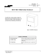
BOX-7355-1 Metal Indoor Enclosure Product/Technical Bulletin 3
I
nstallation
Use the following instructions to mount the enclosure
and the C-7355 time clock. Refer to the time clock
instructions for an exploded illustration of the time
clock.
1. Remove the enclosure cover.
2. Remove the appropriate enclosure knockout to be
used.
3. Using the back of the enclosure as a template,
mark the location of the three mounting holes.
See Figure 3.
4. Mount the back of the enclosure at the marked
locations using field supplied hardware.
5. Connect conduit hubs to conduit before connecting
the hubs to the enclosure.
6. Tighten hub lock nut to the enclosure.
7. Remove the clear cover from the front of the time
clock.
8. Using a screwdriver, loosen the two captive
screws located in the upper and lower corners of
the time clock housing.
9. Remove the time clock housing by pulling forward.
10. Remove the time clock terminal cover by pulling
forward.
11. Secure the time clock terminal base to the
enclosure back using the two 1/2 in. Phillips-head
screws provided with the enclosure. See Figure 3
for mounting hole locations.
12. Make wiring connections (refer to
Wiring
section of
the time clock instructions). Using pliers, remove
the appropriate knockouts on the terminal cover for
wire entry.
13. Replace the time clock terminal cover and housing;
tighten the captive screws; and replace the clear
cover.
14. Place the enclosure cover on the enclosure back
by sliding it downward over the back.
15. Secure the enclosure cover to the back using the
self-tapping 1/2 in. hex-head screw provided with
the enclosure. See Figure 4 for screw location.
C-7355-7, -8, -9
Time Clock
Mounting Holes
Enclosure
Mounting Hole
Enclosure
Mounting Holes
Screw
Terminal Base
Enclosure Back
C-7355-10
Time Clock
Mounting Holes
Align the mounting
holes of the time
clock's terminal
base with the
mounting holes
shown above for
the appropriate
time clock and
secure with the two
1/2 in. Phillips-head
screws provided.
Figure 3: Enclosure and Time Clock
Mounting Holes
Insert padlock (if desired)
for added security.
Insert the provided self-tapping
1/2 in. hex-head screw to secure
the enclosure cover to the back.
Figure 4: Enclosure Cover Holes


