Installing the IP Module
!
Before installing the IP module, make sure the
control panel is NOT connected to the power
supply.
The IP module can be installed in the metal ABS-M box
and in the ABS-P plastic one, as shown respectively in
Figures 2 on page 16 and in Figure 3 on page 17 (part
no.
24b
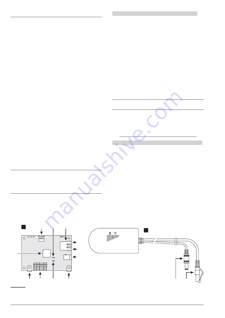
) and described below (see Figure 1 on page 15
and Figure 7).
1.
Insert the IP module to the connector
6
(TCP-IP),
making sure that the holes in the angular brackets
110
on the Module coincide with the holes
5
on the
motherboard.
!
The IP Module may be severely damaged if not
properly inserted.
2.
Secure the IP module to the holes
5
, using the
screws provided.
3.
Connect connector
106
to the LAN via an Ethernet
cable, or refer to the next paragraph if you plan to
install the
ABS-VAP11G
WiFi bridge (not sup-
plied).
!
If you use the Ethernet port of an ADSL modem
wired to an aerial PSTN line, there is the risk
that lighting surges can reach the IP Module
damaging it. To mitigate this risk we recom-
mend to install a surge protector for CAT5/6/7
RJ45 data lines.
+
Use a category 5 (or better) shielded Ethernet ca-
ble (STP or FTP): use a “straight cable” like the one
in Figure 8a on page 24 to connect to a hub/switch;
use a “crossover cable”, like the one in Figure 8b
on page 24 for direct connection to a PC.
4.
Program the options for the IP module: see
“PROGRAMMING FROM THE PC > IP”.
Installation of the ABS-VAP11G in the Metal Container
To install the ABS-VAP11G in the ABS-M metal box,
proceed as described below (Figure 2 on page 16).
1.
Pass connector
114
and connector
115
of
ABS-VAP11G through hole
43
in the bottom of the
control panel.
2.
Connect connectors
114
and
115
of the ABS-VAP11G
connectors
106
and
109
of the IP Module respectively.
!
DO NOT use the USB power supply adaptor
provided with the ABS-VAP11G to connect the
115 connector to the USB port on the Control
Panel (22).
3.
Fix the ABS-VAP11G to top of the control panel
container using the double-sided adhesive, in the
position shown in Figure 2 on page 16.
+
DO NOT place the ABS-VAP11G inside the metal
container of the control panel.
4.
Configure the ABS-VAP11G as indicated in the in-
structions, which can be downloaded from the fol-
lowing page:
http://vonets.com/ProductViews.asp?D_ID=86
Installation of the ABS-VAP11G in a Plastic Container
To install the ABS-VAP11G in the ABS-P plastic con-
tainer, proceed as described below (Figure 3 on page 17).
1.
Connect
connectors
114
and
115
of
the
ABS-VAP11G to connectors
106
and
109
of the IP
Module respectively.
!
DO NOT use the USB power supply adaptor
provided with the ABS-VAP11G to connect the
115 connector to the USB port on the Control
Panel (22).
2.
Secure the ABS-VAP11G cables to hook
76
with a
cable tie.
ABSOLUTA Plus
MOUNTING THE COMPONENTS
23
110
104
113
112
111
110
109
107
115
114
a
105
106
108
b
Figure 7
Parts of the
ABS-IP
Module (
a
) and the
ABS-VAP11G
WiFi Bridge (
b
).


