1053681-UIM-B-0514
4
Johnson Controls Unitary Products
LOCATION
Location is usually predetermined. Check with owner’s or dealer’s
installation plans. If location has not been decided, consider the follow-
ing in choosing a suitable location:
1. Select a location with adequate structural support, space for service
access, clearance for air return and supply duct connections.
2. Using hanging brackets to wall mount this single piece air handler
unit is not recommended.
3. Normal operating sound levels may be objectionable if the air han-
dler is placed directly over some rooms such as bedrooms, study,
etc.
4. Select a location that will permit installation of condensate line to an
open drain or outdoors allowing condensate to drain away from
structure.
5. When an evaporator coil is installed in an attic or above a finished
ceiling, an auxiliary drain pan should be provided under the air han-
dler as is specified by most local building codes.
6. Proper electrical supply must be available.
7. If unit is located in an area of high humidity (i.e. an unconditioned
garage or attic), nuisance sweating of casing may occur. On these
installations, unit duct connections and other openings should be
properly sealed, and a wrap of 2” fiberglass insulation with vinyl
vapor barrier should be used.
CONDENSATE DEFLECTOR
The condensate deflector comes attached to the vertical, A-coil drain
pan. If installing the unit in the upflow or downflow position, no modifica-
tion is necessary.
For units to be installed in the horizontal position, the condensate
deflector needs to be removed from the vertical drain pan and placed
on the horizontal drain pan. Remove the condensate deflector and the
S-clips that attach it to the vertical drain pan. Relocate the deflector and
S-clips onto the horizontal drain pan. Line up with the coil support
bracket. See Figure 5 for details. This positions the deflector below the
feeder tubes to channel the condensate into the drain pan.
AIR HANDLER CONFIGURATION
These air handler units are supplied ready to be installed in an upflow
and right horizontal position. If the unit requires either downflow or left
airflow configurations, the unit must have the coil assembly reposi-
tioned.
The primary and secondary drain line must be trapped to allow proper
drainage of condensate water. The secondary drain line should be
piped to a location that will give the occupant a visual warning that the
primary drain is clogged. If the secondary drain line is not used, it
must be capped.
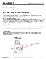
NOTICE
FIGURE 3:
Typical Installation
For both right and left horizontal applications, the condensate deflec-
tor needs to be removed from the vertical drain pan and placed on the
horizontal drain pan. See ìCondensate Deflectorî section for details.
Conversion must be made before brazing the refrigerant connections
to the coil.
UPFLOW
HORIZONTAL RIGHT
HORIZONTAL LEFT
HEAT
HEA
T
HEA
T
DOWNFLOW
HEAT
NOTICE
NOTICE