Johnson Controls 13 SEER - THGD Installation Manual Download Page 14

Subject to change without notice. Printed in U.S.A.

359513-UIM-A-0408

Copyright

 ©

 2008 by Johnson Controls, Inc. All rights reserved.

Supersedes: Nothing

Johnson Controls Unitary Products

5005 York Drive

Norman, OK 73069

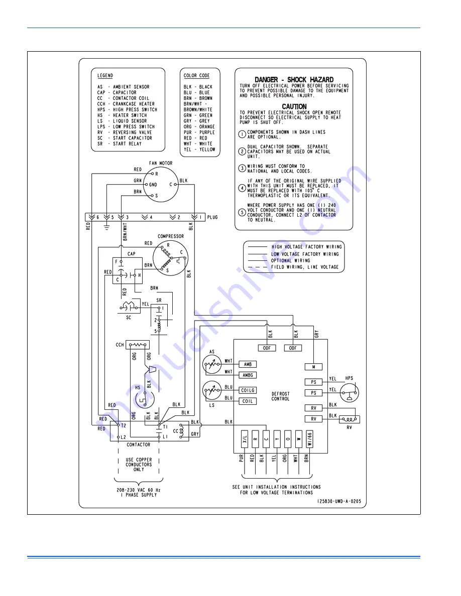
SECTION X: WIRING DIAGRAM

 FIGURE 13:  

Wiring Diagram - Single Phase

Summary of Contents for 13 SEER - THGD

Page 1: ...As soon as a unit is received it should be inspected for possible dam age during transit If damage is evident the extent of the damage should be noted on the carrier s delivery receipt A separate req...

Page 2: ...o the outdoor unit Provide an adequate structural support ADD ON REPLACEMENT RETROFIT The following steps should be performed in order to insure proper sys tem operation and performance 1 Change out o...

Page 3: ...al vapor lines at least 1 every 20 feet toward the outdoor unit to facilitate proper oil return PRECAUTIONS DURING LINE INSTALLATION 1 Install the lines with as few bends as possible Care must be take...

Page 4: ...rts except when necessary for servicing the system 12 Release the refrigerant charge into the system Open both the liq uid and vapor valves by removing the plunger cap and with an allen wrench back ou...

Page 5: ...r and remove from unit 3 Run power wiring from the disconnect switch to the unit 4 Route wires from disconnect through power wiring opening pro vided and into the unit control box as shown in Figure 5...

Page 6: ...if the relative humidity in the space is higher than the desired set point of the dehumidification control the variable speed blower motor will operate at lower speed until the dehumidification con t...

Page 7: ...A DN22U00124 THERMOSTAT Part Numbers SAP Legacy 67297 031 01975 E B E ZD E R OD MODELS HGD HP RHS O Reversing Valve Energized in Cool C 24 Volt Common R 24 Volt Hot W1 66 out Heat Y Compressor DEMAND...

Page 8: ...Heat XFMR R 24 Volt Hot Cool XFMR Part Numbers SAP Legacy 67297 031 01975 E B E ZD E R OD MODELS HGD HP RHS O Reversing Valve Energized in Cool C 24 Volt Common R 24 Volt Hot W1 66 out Heat Y Compres...

Page 9: ...weighing device is avail able add refrigerant accordingly Otherwise model specific charging charts are provided on the units rating plate for cooling mode only There is no accurate method for chargin...

Page 10: ...6 93 206 103 236 113 88 52 118 68 148 82 178 94 208 104 238 114 90 54 120 69 150 83 180 94 210 105 240 114 92 55 122 70 152 84 182 95 212 105 242 115 94 56 124 71 154 84 184 96 214 106 244 115 96 57 1...

Page 11: ...e defrost cycle it will terminate the defrost cycle and de energize the compres sor The control will also stop the defrost cycle length timer but not reset it When the control receives another call fo...

Page 12: ...e state of the liquid line temperature and outdoor ambient tem perature inputs The coil does not have to be cold and the outdoor tem perature does not have to be within a certain range for the heat pu...

Page 13: ...s reset the control will stop displaying the fault code and will respond to thermostat inputs normally INDICATIONS OF PROPER OPERATION Cooling Cooling operation is the same as any conventional air con...

Page 14: ...ted in U S A 359513 UIM A 0408 Copyright 2008 by Johnson Controls Inc All rights reserved Supersedes Nothing Johnson Controls Unitary Products 5005 York Drive Norman OK 73069 SECTION X WIRING DIAGRAM...

Reviews: