23
Sales/Spares & Replacement Help Line 01604 762881
14.
CONNECTIONS & FILLING
NOTES.
Ensure all boss blanking plugs are removed before connecting hardware. Each valve must be fitted to the correct
boss as shown. See Figure 25.
Ensure each union is fitted with fibre seals provided. On the DHW inlet use the filter washer provided. DO NOT use
a fibre seal.
Do not subject any of the isolating valves to heat as the seals may be damaged.
14.1
WATER CONNECTIONS CH
14.1.1 Connect the CH flow service valve (black handle) and copper tail provided in the hardware pack to the
threaded boss connection provided at the lower rear of the boiler.
14.1.2 Connect the CH return valve (black handle) and copper tail.
14.2 GAS
CONNECTION
IMPORTANT.
The gas service cock is sealed with a non-metallic blue fibre washer, which must not be overheated
when making capillary connections. See Figure 23 for details of the position of the gas connection.
14.2.1 For additional information of the Gas Supply see paragraph 4.3.
14.3 CONDENSATE
DRAIN
14.3.1 The condensate drain tube is secured by a cable tie when packed. This cable tie needs to be cut and
removed before connecting to the condensate drain hose. Remove the bung from the pipe.
14.3.2 Connect the condensate drain tube.
14.4
PRESSURE RELIEF VALVE DRAIN
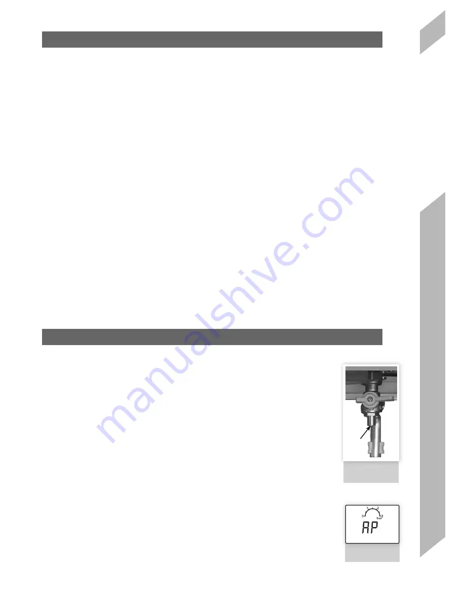
14.4.1 The drain comprises of a 15mm diameter stub pipe. See Figure 23.
14.4.2 The discharge pipe should be positioned so that the discharge of water or steam cannot create a hazard
to the occupants of the premises or damage the electrical components and wiring.
14.5
FILLING THE BOILER
IMPORTANT.
When filling, there may be a slight water leak from the air vent therefore electrical connections must
be protected.
14.5.1 Ensure Filling Loop is connected.
14.5.2 Ensure the cap on auto air vent is open. (In the up position)
14.5.3 Check all isolation handles on all water connections are in the open position.
14.5.4 Open the black handle (G) on the filling loop, then slowly open the black handle (F) until the pressure
gauge reads between 1 to 1.5 bar. When reached closed the isolation valves.
14.5.5 Disconnect the left hand filling loop, retain the top hat washer and using the blanking caps, cap off the
connection and the end of the filling loop.
14.5.6 Connect extended blanking cap and top hat washer to filling loop pipe.
NOTE:
Fully open all DHW taps and ensure water is flowing freely.
15. COMMISSIONING
15.1
CHECK GAS INSTALLATION
15.1.1 The whole of the gas installation, including the meter, should be inspected and tested
for tightness and purged in accordance with the recommendations of BS. 6891. In IE
refer to IS.813.
15.1.2
Purge air from the gas installation by the approved methods only.
PLEASE
NOTE:
The combustion for this appliance has been checked, adjusted and
preset at the factory for operation on the gas type defined on the appliance data plate.
A flue Gas Analyser measurement
is a recommendation from April 2013 and a
requirement from April 2014
. Do not adjust the air/gas ratio valve.
15.1.3 Having checked the boiler has been installed in accordance with these instructions.
The integrity of the flue system and the flue seals, as described in the Flue Installation
section. Proceed to put the boiler into operation as follows:
15.2
AIR PURGE FUNCTION
15.2.1
During this function, heat demand is switched off and fan will run at maximum for 120
seconds.
15.2.2
Also at the same time, the supply pump will be switched on for 5 seconds and off for 5
seconds continuously.
15.2.3
Diverting 3 way valve will move to the CH position for the first 30 seconds and then to
the DHW position. This will be repeated.
15.2.4
This way, air bubbles dissipate and normal operation of the supply pump is secured.
15.2.5
Function can be skipped by pressing the K4 button. This function can be activated in
the following conditions:
a. If the controller is plugged in to the Mains for the first time.
b. After a manual reset to reset the lockout fault E03. High limit temperature protection.
c. When the central heating water pressure is built up to the normal level after the fault
F37 or fault F40.
15.2 .6 If there is no heat demand afterwards, the controller will switch to standby mode.
FIGURE 23.
GAS PRESSURE
TEST POINT
FIGURE 23
FIGURE 24.
LED READ OUT
FIGURE 24
TEST
POINT


