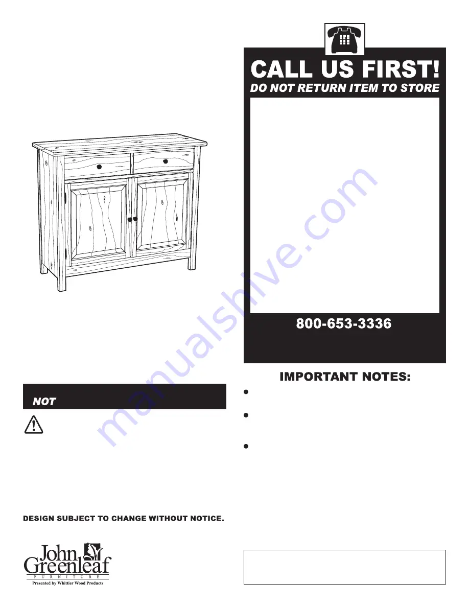
John Greenleaf 384W Assembly Instructions Manual Download Page 1

Model #

384W

Rustic Sideboard

Assembly Instructions

10/05

For normal household use only. 

 recommended for commercial use.

Congratulations!

This fine piece of furniture will make a handsome 
addition to your home. For the best results, start by 
reading both the Assembly Instructions and 
Finishing Hints before you begin your project.

Do not climb, sit or stand on this piece of 
furniture.

Unload items from this unit prior to moving. 

Do not overload shelves and drawers on this unit.

Before loading or moving this unit, check all screws 
and supports for tightness. 

For maximum stability, attach unit to the wall using 
the enclosed hardware as per instructions.

Production Code:

  Read both the Assembly Instructions and Finishing 

Hints completely before beginning. 

  Store the parts: 1) in their box; 2) in a dry place; 3) in 

temperatures ranging from 40° to 90°. (Not on a cold, 
possibly damp, cement floor.) 

  Inspect your furniture periodically for any loose glue 

joints or screws, or any other problem which may 
be affecting the stability of your furniture. Tighten or 
repair as needed.

Service Policy:


We will replace any parts 

which  are defective, missing or damaged 
during assembly. Please contact Whittier 
Wood Products customer service department 
directly (by phone, fax, mail or email) for 
replacement parts.

Hours:

 Our friendly customer service staff 

can be reached Monday-Friday 7:00 a.m. to 
5:00 p.m. (Pacific Time). A message can be 
left 24 hours a day, 7 days a week. 

To Order:

 Provide the complete furniture 

model number (upper left corner of this 
page), part letter, production code, quantity 
needed, reason for replacement and your full 
name and address along with a telephone 
number in case we need to contact you.

Parts ship from our Eugene, Oregon factory 
within 1 or 2 business days from the time 
we receive the request. Please allow 5-10 
business days for delivery.


Outside U.S. or Canada: 541-687-0213

Fax: 541-687-2060 • Email: [email protected]

Mail: P.O. Box 2827 • Eugene, Oregon 97402, U.S.A.

P.O. Box 2827
Eugene, OR 97402 USA

Natural characteristics 

such as knots provide a 

natural feel.

Summary of Contents for 384W

Page 1: ...ose glue joints or screws or any other problem which may be affecting the stability of your furniture Tighten or repair as needed Service Policy We will replace any parts which are defective missing o...

Page 2: ...e parts received match those on the parts list below A Bottom Shelf Qty 1 B Base Qty 1 C Left Side Assembly Qty 1 D Sleeper Qty 2 E Right Side Assembly Qty 1 F Top Qty 1 L Adjustable Shelf Qty 1 H Dra...

Page 3: ...imilar conditions for a day or so N Wood Dowel Qty 6 384W Rustic Sideboard Parts List cont O Rafix Cam Qty 4 P Rafix Bolt Qty 4 T 8x1 Black Screw Qty 12 V 6x1 2 Philtruss Screw Qty 28 X Tack Glide Qty...

Page 4: ...ore than one type of hardwood is used we recommend testing for desired color To test stain for desired color on a Veneer parts apply stain to unexposed portion of Bottom Shelf A See FIGURE 3 b Alder p...

Page 5: ...rger holes near the top edge of each Side Assembly C E Screw four Rafix Bolts P into the Top F Screw Cam Connectors Q Two in each Side Assembly C E Four in the Base B FIG 2 TOP VIEW O O x4 P x4 READ C...

Page 6: ...lel with the front edge of the legs See FIGURE 4 Attach the Bottom Shelf Assembly A B to the Left Side Assembly C gluing the Wood Dowel N in the Left Side Assembly C into the Base B Fasten Bottom Shel...

Page 7: ...Cams O Secure the upper Sleeper D to the Top F using Screw T through the pre drilled holes in the upper Sleeper D See FIGURE 6 T x4 O x4 5 Rotate Left Side Assembly and set in place on the right Side...

Page 8: ...is longer tap bottom of Right Side Assembly E See FIGURE 7A Connect the two Backs G together using the Plastic H Channel U Make sure to connect the edges that do not have pre drilled holes See FIGURES...

Page 9: ...rear The measurements should be equal If one is longer hold the drawer by the corners on the longest line and squeeze them together until square See FIGURE 10B Attach two Knobs ZB to the Drawer Face K...

Page 10: ...e of the lower Sleeper D Make sure the back of the Magnetic Catch ZF is flush with the back edge of the lower Sleeper D Use the pan head screws provided in the kit to secure the catch in place See FIG...

Page 11: ...E 14B Attach a Knob ZB to each door using a 1 Machine Screw ZI See FIGURE 14C FIG 14A FIG 14B ZB x2 ZI x2 ZH x8 FIG 14C 13 Attach two Minaret Hinges ZG to each Door M Align the outermost hole in each...

Page 12: ...eed to be level and have equal gaps all the way around Adjust one door at a time by slightly loosening the four Screws ZH in each hinge The oval screw holes in the hinges allow some adjustment of the...

Reviews: