Johansson 6505UK Use Manual Download Page 4

Programming

4

OPERATION

1 2 3 4 5 6 7 8 9

Split UHF

Filter & Input Selection

Start

Stop

Level

Split UHF

Filter & Input Selection

Start

Stop

Level

Preset : 01~40

Preset : 01~40

VHF

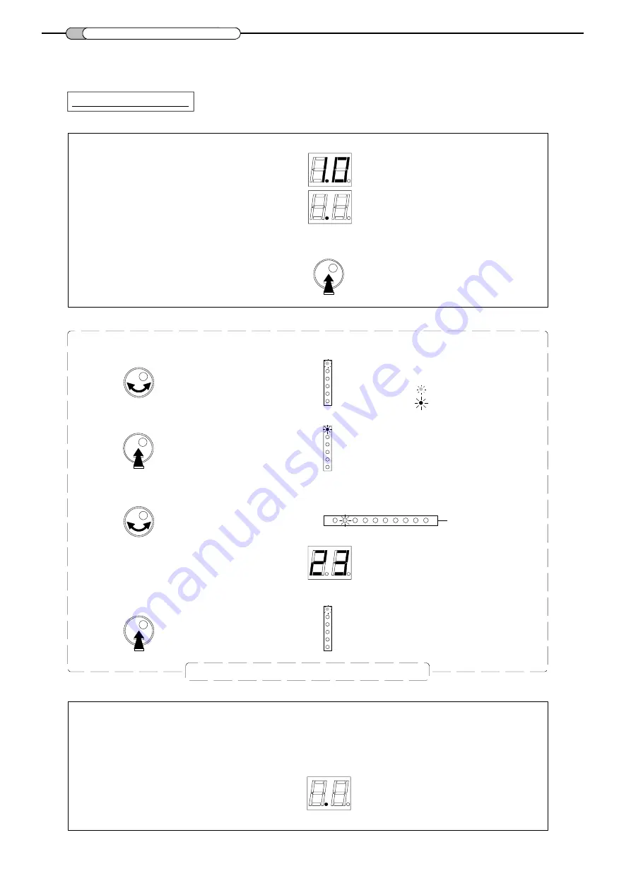
All parameters  are  set  with the rotary push button.
Each function and parameters  are  shown on 2  digits  display  and different LEDs .

- Make all the necessary connections and connect the equalizer to mains.

- Push on the rotary button for more than 3 seconds to enter  into  programming mode.

3sec.

- Turn the button to select the desired mode.

- Push the rotary button to enter the selected mode.

- Inside the mode, turn the button to select the parameter
   (input, cluster, channels, level...)

- Push the button to confirm the parameter setting.

The software version is displayed,

Mode is indicated with
a GREEN colored LED.

The LED is now RED colored.

Cluster LEDs

Display

LED returns to a GREEN color.

followed by a dot.

= green LED

= red LED

Repeat this section to set all parameters

Split UHF

Filter & Input Selection

Start

Stop

Level

Preset : 01~40

The equalizer will go in "stand-by" and will display a dot after 1 minute 
if the rotary / push button is not activated.

Summary of Contents for 6505UK

Page 1: ...igits display and LEDs for each cluster 40 presets of configuration see list in annex Accurate equalization of levels using 1 dB step attenuators Switchable input amplifier to attenuate high input sig...

Page 2: ...ion Do not place any items such as newspapers table cloths curtains on the unit that might cover the ventilation holes The unit must not be exposed to any source of heat sun heater Do not place any na...

Page 3: ...5V DC DC DC DC DC Grounding 2 digits display LED for Clusters D C Power pass switch Rotary push button Mains 230 240 V Headend amplifier DC Power pass switch DC DC Mode Function LED Split UHF MULTI C...

Page 4: ...mode 3sec Turn the button to select the desired mode Push the rotary button to enter the selected mode Inside the mode turn the button to select the parameter input cluster channels level Push the but...

Page 5: ...e button to select the desired preset number Push the button to confirm LED is green Example preset n 17 Preset 01 40 Preset 01 40 LED is red Preset 01 40 Notes In the preset mode 01 to 40 the channel...

Page 6: ...cluster has to be switched off park function Set the cluster to channel 00 see Setting channels cluster Push the button to confirm UHF 1 clusters are indicated by the RED LEDs n 1 to 9 UHF 2 clusters...

Page 7: ...side the mode turn the button to select the cluster to be set Setting channels cluster Each UHF cluster has a bandwidth which can be programmed from 1 to 2 channels Each VHF cluster has one channel ba...

Page 8: ...s will blink alternately Channel Cluster 2 Cluster 1 Turn the button to select Filter Input Selection Puch the rotary button to enter the selected mode LED is red LED is green Turn the button to choos...

Page 9: ...the button to select cluster 2 Push the button to confirm Turn the button to select the Level mode Push the rotary button to enter the selected mode Turn the button to set the level variable from 30...

Page 10: ...ct the input to be attenuated Turn the button to select the input Turn continuously the button through every cluster to have access to the input selection Push the button to confirm Turn the button to...

Page 11: ...LE FILTER EQUALIZER OUT UHF Filter Input Selection Start Stop VHF Level 2 F H U 1 F H U Ref 6505 Digital Terrestrial DC UHF1 DC UHF2 GND 5V 500 mA VHF 2 3 4 5 6 7 8 9 UHF1 UHF2 1 VHF OUT DC Preset 01...

Page 12: ...v Frankrijklaan 27 B 8970 Poperinge Belgium FAX 32 5733 4524 e mail sales johansson be TEL 32 5733 3363 www johansson be R 1 2 3 4 5 6 7 8 9 VHF BIII 2 F H U 1 F H U DC UHF OUTPUT DC1 DC2 9 VHF OUTPUT...

Reviews: