jobmate 199-8594-6 Use And Care Manual Download Page 22

22

Troubleshooting

10. t

roubleShooting

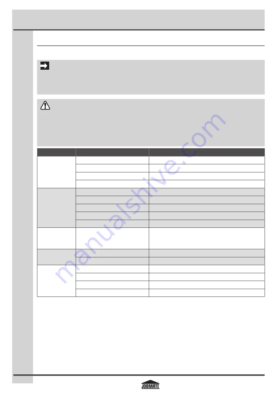
The following chart lists common issues and solutions. Please read it carefully and follow all instructions closely.

IMPORTANT

If your unit still is not functioning properly once you have used this guide, please call the JOBMATE toll-free service number at 

1-866-JOBMATE 

(1-866-562-6283).  Please do NOT bring the unit back to the store until you have called this number.

WARNING


IF ANY OF THE FOLLOWING SYMPTOMS APPEARS WHILE THE WELDER IS IN USE, TURN IT OFF AND DISCONNECT THE WELDER FROM 
THE POWER SUPPLY IMMEDIATELY. FAILURE TO HEED THIS WARNING WILL RESULT IN SERIOUS PERSONAL INJURY OR DEATH.


REPAIRS MUST BE PERFORMED BY A QUALIFIED SERVICE TECHNICIAN ONLY.

PROBLEM

POSSIBLE CAUSE

SOLUTION

The welder does 
not work when 
the main switch is 
turned on.

No power input.

Check the circuit or fuse of the power supply.

Power cord or power plug is broken.

Replace the power cord.

Main switch is broken.

Replace the main switch.

Transformer is broken

Replace the transformer.

The welder does not 
weld.

Incorrect power input.

Check the power source.

Inadequate current at the output.

Check for proper grounding to the workpiece.

Poor connection of output cable.

Check the output connection.

Dirty surfaces.

Clean the surfaces.

Wrong welding wire.

Use the correct wire.

Blown fuse or 
tripped circuit 
breaker.

Inadequate fuse or circuit breaker.

Check whether the fuse in power supply is 20 A.

Arc is hard to start.

Wrong welding wire.

Use the correct wire.

Base metal not grounded properly.

Make sure the connection is good.

Inconsistent arc or 
wire feed.

Not enough drive roller pressure.

Tighten the drive tension adjustor on wire feeder. 

Spool hub tension too tight or loose.

Adjust the wing nut on the spool holder. 

Contact tip worn or wrong size.

Replace the contact tip. 

Rusty or corroded wire.

Replace the wire. 

Summary of Contents for 199-8594-6

Page 1: ...20 A branch circuit DO NOT REMOVE THIS LABEL N ENLEV EZ PAS CETTE TIQUET TE 229683 If connecte d to a circuit protected by fuses use a time dela yed fuse marked D Cette soudeuse requiert un circuit de...

Page 2: ...se requiert un circuit de 20 A Se la soudeuse est branch e un circuit prot g par fusibles utilisez un fusible temporis marqu D 1 1 2 WIRE FEED ENTRAI NEMEN T 199 8594 6 SOUDEUSE A D VIDAGE DE FIL LECT...

Page 3: ...g the appropriate drive roller 11 5 3 Pre adjustments 12 5 4 Setting the wire feed speed 13 5 5 Assembling the hand held welding shield 14 6 Operating Instructions 14 18 6 1Tuning in the wire speed 14...

Page 4: ...ry IMPORTANT Installation operation or maintenance information which is important but not hazard related READ INSTRUCTION MANUAL 1 2 Safety warnings RISK OF ELECTRIC SHOCK Do not touch electrical live...

Page 5: ...bly available from the manufacturer or its service agent GENERAL SAFETY RULES WARNING DONOTUSETHEWELDERINTHEPRESENCEOFFLAMMABLE LIQUIDS OR GASES SPARKS THAT ARE CREATED DURING USEMAYIGNITEGASES DONOTO...

Page 6: ...nd MIG gun torch The welding wire is driven through the welding cable and the MIG gun torch to the workpiece It is attached to the drive system and the gun trigger activates the drive motor Thermal in...

Page 7: ...Polarity changing Factory polarity setting electrode negative is for flux core welding no shielding gas is required In this process the RED gun lead is connected to the negative polarity terminal and...

Page 8: ...s such as wire spool 1 driving mechanism 2 and a set up chart 3 The driving mechanism has an inlet guide tube 4 and an outlet guide tube 5 for guiding the wire across the drive roller JM 1998594 04 NO...

Page 9: ...sories from the carton Make sure that all items listed in the packaging contents are included Inspect the tool carefully to make sure no breakage or damage occurred during shipping Do not discard the...

Page 10: ...VEZ PAS CETTE TIQUE TTE 229683 If connect ed to a circuit protecte d by fuses use a time de layed fuse marked D Cette soudeus e requiert un circuit de 20 A Se la soudeus e est branch e un circuit prot...

Page 11: ...06 figB 2 1 3 Place the wire spool 1 over the spool hub 2 Place the roller plate 3 spring 4 and wing nut 5 above the wire spool one by one Tighten the wing nut fig C JM 1998594 07 figC 1 2 3 4 5 Note...

Page 12: ...FORE INSTALLING REMOVE ANY OLD WIRE FROM THE MIG GUN ASSEMBLY TO PREVENT THE WIRE FROM BEING JAMMED INSIDETHE GUN LINER USE EXTREME CAUTION WHEN REMOVING THE WELDING NOZZLE AS THE CONTACT TIP ON THE W...

Page 13: ...efer to page 11 for set up chart on the back side of the wire drive compartment 14 Set the wire speed control Straighten the MIG gun cable and pull the trigger in the gun handle to feed the wire throu...

Page 14: ...tuned in before starting the welding operation and whenever the heat setting wire diameter or wire type are changed 6 2 Current overload button The overload button 1 is used to control the wire feed...

Page 15: ...improve the visibility of the arc in relation to the weld puddle and to direct the force of the arc fig O 4 Turn the wire speed adjustment knob with the other hand to its maximum position and continu...

Page 16: ...s pull the torch alongtheweldjointforgreaterweldpuddlevisibility figR fig R JM 1998594 22 1 2 Travel speed The rate at which the torch is being pushed or pulled along the weld joint For a fixed heat s...

Page 17: ...the most difficult welding position For this position angle A should be maintained at 60 degrees Maintaining this angle will reduce falling of molten metal into the nozzle fig X Angle B should be zero...

Page 18: ...es a weld with the most finished appearance In this method a hole is punched or drilled into the top piece of metal and the arc is directed through the hole to penetrate into the bottom piece The pudd...

Page 19: ...ce worn or broken parts X The welder needs regular maintenance as follows Clean the dust dirt and grease periodically from the welder Every six months remove the front panel from the welder to clear t...

Page 20: ......

Page 21: ...ainCircuitChart 9 Main Circuit Chart JM 1998594 35 Welding gun switch Circuit Breaker Welding gun 2 3 4 5 2 1 2 1 _ _ _ _ 2 2 3 4 3 1 1 S1 T1 J G L S2 S3 PCB MAX fan 1 R T 24V MIN _ NO GAS GAS Earth c...

Page 22: ...or fuse of the power supply Power cord or power plug is broken Replace the power cord Main switch is broken Replace the main switch Transformer is broken Replace the transformer The welder does not w...

Page 23: ...e ups or adjustments e this warranty will not apply where damage is caused by repairs made or attempted by others i e persons not authorized by the manufacturer f this warranty will not apply to any p...

Page 24: ......

Page 25: ......

Reviews: