


english
17
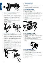
4 MAINTENANCE
when executing any maintenance operation, it is necessary to complete the following
requirements:
•
never carry out any operation while the machine is running.
•
the power cable must be disconnected from the electrical connection.
•
the instructions in this manual must be followed strictly.
•
use original spare parts.
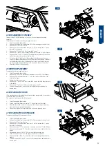
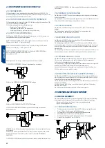
4.1 REPLACEMENT Of THE CUTTER
to replace the cutter, proceed as follows:
•
turn off and unplug the machine.
•
insert rod “a” supplied with the accessories into the hole that blocks the
rotation of the head. to find it, turn the head by hand.
•
with the fixed key “b” which is also supplied together with the accessories,
loosen nut “e”. take into account that nut “e” has a left-handed thread.
•
remove the worn cutter “c”.
•
install the new cutter “c”, and tighten it by tightening nut “e”. check that the
cutter is mounted with its cutting teeth pointed in the correct position. take into
account that the cutter rotates clockwise.
•
remove rod “a”.
•
after replacing the cutter, it is recommended to carry out the “cutting depth
adjustment”. this procedure is indicated in section 3.1.2 of this Manual.
A
B
C
E
4.2 REPLACING THE PROBE
to replace the probe, proceed as follows:
•
turn off and unplug the machine.
•
loosen screw “F”, using allen key number 4 supplied with the accessories.
•
remove the worn “t” probe.
•
install the new “t” probe. Make sure that the rear part of the probe rests
against the support “g”, and tighten screw “F”.
•
after replacing the probe, it is recommended to carry out the “cutting depth
adjustment”. this procedure is indicated in section 3.1.2 of this Manual.
G
T
F
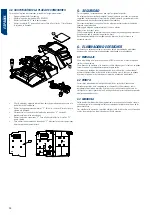
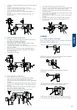
4.3 BRUSH REPLACEMENT
to replace the brush, proceed as follows:
•
turn off and unplug the machine.
•
insert rod “a” supplied with the accessories into the hole that blocks the
rotation of the head. to find it, turn the head by hand.
•
loosen screw “h”, using allen key number 4 supplied with the accessories.
•
remove the worn brush “J”.
•
install the new brush “J” and tighten it by tightening screw “h”. do not tighten
it too hard, so that in the next replacement of the brush, the “h” screw can be
easily released.
•
remove rod “a”.
A
J
H
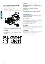
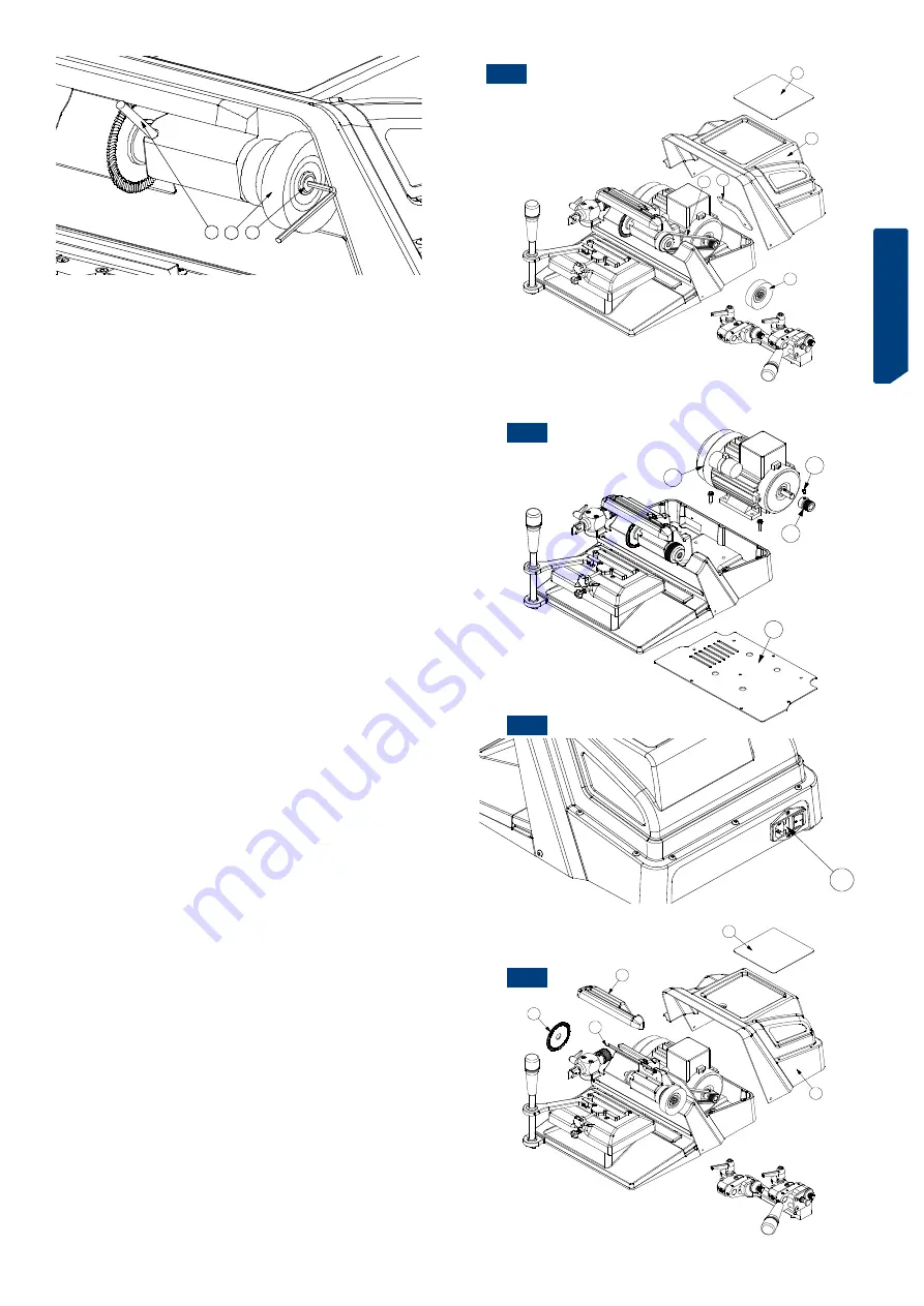
4.4 REPLACEMENT Of THE BELT
the belt of the Volga-bit machine is elastic, so it does not require tensioning
operations.
if replacement of the belt is necessary, proceed as follows:
•
turn off and unplug the machine.
•
remove the carriage from the machine (bit or clamp carriage for vertical cuts).
•
remove the “K” mat from the top.
•
remove the “n” cover that hides the motor. to do this, release the 11 screws
that hold it to the bench.
•
remove the “o” sheet. to do this, loosen the 2 screws.
•
remove the “J” brush. this procedure is indicated in section 4.3 of this Manual.
•
remove the old “i” belt. to remove it from the pulleys, we manually rotate the
belt at the same time as we force it on the side.
•
Fit the new belt. to do this, point the machine so that the rear part faces us.
First, insert the belt onto the motor pulley. then, place the other end of the belt
on the diameter of the side of the head pulley. Finally, force the belt laterally
while turning the head with the key no. 13 inserted on the nut of the cutter.
•
check that the belt is fitted correctly.
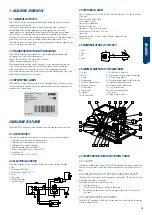
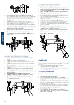
4.5 MOTOR REPLACEMENT
to replace the motor, proceed as follows:
•
turn off and unplug the machine.
•
remove the “i” belt. this procedure is indicated in section 4.4 of this Manual.
•
remove the lower protective plate “P”. to do this, release the 8 screws that
hold it to the bench.
•
unplug the motor power cable.
•
remove the “z” motor. to do this, loosen the 4 screws that hold the motor base
to the bench.
•
remove the “Y” pulley. to do this, loosen the grub screw “X”.
•
to mount the new motor, carry out the same operations described, but in
reverse order.
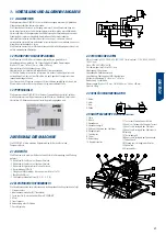
4.6 REPLACING THE fUSES
if the machine does not start when the start-up switches are operated, it is necessary
to check the condition of the fuses.
this operation is performed in the following way:
•
turn off and unplug the machine.
•
using a small screwdriver, remove the “u” fuse holder from the socket.
•
check the fuses with a tester, as it may seem that they are in good condition,
even when they are electrically defective.
•
if necessary, replace the fuses with others of the same type and value.
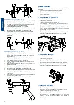
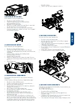
4.7 REPLACING THE LIGHTING LEDS
to replace the lighting leds, proceed as follows:
•
turn off and unplug the machine.
•
remove the carriage from the machine (bit or clamp carriage for vertical cuts).
•
remove the “K” mat from the top.
•
remove the “n” cover that hides the motor. to do this, release the 11 screws
that hold it to the bench.
•
remove the cutter “c”. this procedure is indicated in section 4.1 of this Manual.
•
remove the cutter guard “d”. to do this, release the 3 screws that hold it to the
bench.
•
unscrew the 2 wires of the “9” led strip, from the connection strip.
•
take off the led strip “9” from the support on which it is attached.
•
remove the strip of leds “9”, so that their cables exit through the hole in the
support.
•
to mount the new led strip “9”, carry out the same operations described, but in
reverse order.
K
N
C
D
9
U
P
Z
Y
X
K
N
J
I
O
4.4
4.5
4.6
4.7
Summary of Contents for VOLGA BIT
Page 2: ......
Page 3: ...Espa ol VOLGA BIT MANUAL DE INSTRUCCIONES M QUINA DUPLICADORA...
Page 11: ...english VOLGA BIT USER manual KEY CUTTING MACHINE...
Page 19: ...deutsch VOLGA BIT Anweisungshandbuch KOPIERMASCHINE...
Page 28: ...deutsch 28...
Page 29: ...francaise VOLGA BIT MANUEL D INSTRUCTIONS MACHINE A REPRODUIRE...
Page 38: ...francaise 38...
Page 39: ...portuguese VOLGA BIT Manual de instru es M QUINA DUPLICADORA...
Page 47: ...portuguese 47...
Page 48: ...portuguese 48...
Page 49: ...POLISH VOLGA BIT PODR CZNIK U YTKOWNIKA maszyna do kopiowania...


