


SECTION 7 - GENERAL ELECTRICAL INFORMATION & SCHEMATICS
31215923
7-11
7.6
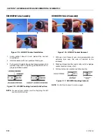
WORKING WITH DEUTSCH CONNECTORS
DT/DTP Series Assembly
1. Grasp crimped contact about 25 mm behind the con-
tact barrel.
2. Hold connector with rear grommet facing you.
3. Push contact straight into connector grommet until a
click is felt. A slight tug will confirm that it is properly
locked in place.
4. Once all contacts are in place, insert wedgelock with
arrow pointing toward exterior locking mechanism.
The wedgelock will snap into place. Rectangular
wedges are not oriented. They may go in either way.
NOTE:
The receptacle is shown - use the same procedure for
plug.
DT/DTP Series Disassembly
1. Remove wedgelock using needlenose pliers or a
hook shaped wire to pull wedge straight out.
2. To remove the contacts, gently pull wire backwards,
while at the same time releasing the locking finger
by moving it away from the contact with a screw-
driver.
3. Hold the rear seal in place, as removing the contact
may displace the seal.
Figure 7-12. DT/DTP Contact Installation
A
B
C
D
Figure 7-13. DT/DTP Contact Removal
A
B
C
Summary of Contents for ERT2669
Page 2: ......
Page 4: ...INTRODUCTION A 2 31215923 REVISON LOG Original Issue A January 08 2021...
Page 12: ...viii 31215923 TABLE OF CONTENTS...
Page 40: ...SECTION 1 SPECIFICATIONS 1 22 31215923...
Page 58: ...SECTION 2 GENERAL 2 18 31215923...
Page 187: ...SECTION 4 BASIC HYDRAULIC INFORMATION SCHEMATICS 31215923 4 11...
Page 206: ...SECTION 4 BASIC HYDRAULIC INFORMATION SCHEMATICS 4 30 31215923...
Page 225: ...SECTION 4 BASIC HYDRAULIC INFORMATION SCHEMATICS 31215923 4 49...
Page 242: ...SECTION 4 BASIC HYDRAULIC INFORMATION SCHEMATICS 4 66 31215923...
Page 307: ...SECTION 5 JLG CONTROL SYSTEM 31215923 5 65...
Page 334: ...SECTION 6 LSS SETUP CALIBRATION SERVICE 6 12 31215923...
Page 362: ...SECTION 7 GENERAL ELECTRICAL INFORMATION SCHEMATICS 7 28 31215923...
Page 374: ...SECTION 7 GENERAL ELECTRICAL INFORMATION SCHEMATICS 7 40 31215923...
Page 375: ......


