


SECTION 5 - JLG CONTROL SYSTEM
31215923
5-63
5.6
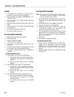
CHASSIS TILT SENSOR INSTALLATION
NOTE:
Refer to Figure 5-14., Chassis Tilt Sensor Removal for
numbers in parenthesis.
1. Disconnect the batteries.
2. Remove the three bolts (2), washers (3) and one gas-
ket (4) to remove the tilt sensors (1) from the Frame.
NOTE:
Follow the above procedures in reverse order when
installing the chassis tilt sensor assembly. Torque
screws should not exceed 135 in. lbs. (15.25 Nm).
NOTE:
After installing, be sure to calibrate the chassis tilt
sensor (refer to Section 5 for calibration procedure.)
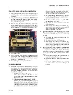
Chassis Tilt Sensor -
If this sensor is not wired correctly
or if you have the wrong part number you will get CAN-
BUS FAILURE - CHASSIS TILT SENSOR
1. Tilt Sensor
2. Frame
3. Angle Chassis Harness
4. Gasket
Figure 5-13. Chassis Tilt Sensor Location
MAF42450
2
1
3
4
1. Tilt Sensor
2. Bolt
3. Washer
4. Gasket
Figure 5-14. Chassis Tilt Sensor Removal
Table 5-1. Tilt Sensor Harness
Function
Connector Pin
+VBAT
1
-VBAT
2
CANL
3
CANH
4
MAF42440
1
3
2
4
Summary of Contents for ERT2669
Page 2: ......
Page 4: ...INTRODUCTION A 2 31215923 REVISON LOG Original Issue A January 08 2021...
Page 12: ...viii 31215923 TABLE OF CONTENTS...
Page 40: ...SECTION 1 SPECIFICATIONS 1 22 31215923...
Page 58: ...SECTION 2 GENERAL 2 18 31215923...
Page 187: ...SECTION 4 BASIC HYDRAULIC INFORMATION SCHEMATICS 31215923 4 11...
Page 206: ...SECTION 4 BASIC HYDRAULIC INFORMATION SCHEMATICS 4 30 31215923...
Page 225: ...SECTION 4 BASIC HYDRAULIC INFORMATION SCHEMATICS 31215923 4 49...
Page 242: ...SECTION 4 BASIC HYDRAULIC INFORMATION SCHEMATICS 4 66 31215923...
Page 307: ...SECTION 5 JLG CONTROL SYSTEM 31215923 5 65...
Page 334: ...SECTION 6 LSS SETUP CALIBRATION SERVICE 6 12 31215923...
Page 362: ...SECTION 7 GENERAL ELECTRICAL INFORMATION SCHEMATICS 7 28 31215923...
Page 374: ...SECTION 7 GENERAL ELECTRICAL INFORMATION SCHEMATICS 7 40 31215923...
Page 375: ......


