


SECTION 4 - BASIC HYDRAULIC INFORMATION & SCHEMATICS
31215923
4-33
3. Steer Relief Valve
a. Instrumentation/Setup:
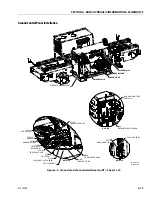
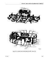
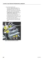
1. Install a pressure gauge, 3000 PSI or higher, at the
M1 port on the main control valve located in the
hydraulic compartment on the right-hand side of
the machine (see Figure 4-22.).
NOTE:
The port will not be directly visible as it is located on
the side of the main control valve facing the back
wall of the hydraulic compartment.
b. Pressure Setting Check
A. Steer Right Relief
1. Start the machine on and running, use the
platform control box to command “Steer Right”
until the wheels have turned as far as they can
(cylinder bottoms out)
2. Note the pressure on the gauge connected to
port “M1” while continuing to command steer
right
3. Adjustment is required if the pressure gauge
reads 50 PSI above or below 2494PSI (172Bar).
Follow the steps from :
Section A, Steer Right Relief
B. Steer Left Relief
1. Start the machine on and running, use the
platform control box to command “Steer Left”
until the wheels have turned as far as they can
(cylinder bottoms out)
2. Note the pressure on the gauge connected to
port “M1” while continuing to command steer
right
3. Adjustment is required if the pressure gauge
reads 50 PSI above or below 1914 PSI
(132Bar).Follow the steps from :
Section B., Steer Left Relief
c. Pressure Setting Adjustment
A. Steer Right Relief
1. Follow steps of steer right relief pressure setting
checks above so that the gauge connected to the
“M1” port is reading the steer right relief setting
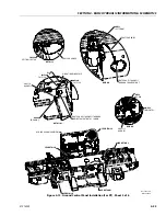
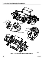
2. Loosen the jam nut on the steer right relief valve
(highlighted green in Figure 4-23.) and turn the
adjustment screw (highlighted red in
Figure 4-23.) clockwise to increase pressure or
counterclockwise to decrease pressure.
Figure 4-22. Location Of Port “M1” (Main Valve)
Summary of Contents for ERT2669
Page 2: ......
Page 4: ...INTRODUCTION A 2 31215923 REVISON LOG Original Issue A January 08 2021...
Page 12: ...viii 31215923 TABLE OF CONTENTS...
Page 40: ...SECTION 1 SPECIFICATIONS 1 22 31215923...
Page 58: ...SECTION 2 GENERAL 2 18 31215923...
Page 187: ...SECTION 4 BASIC HYDRAULIC INFORMATION SCHEMATICS 31215923 4 11...
Page 206: ...SECTION 4 BASIC HYDRAULIC INFORMATION SCHEMATICS 4 30 31215923...
Page 225: ...SECTION 4 BASIC HYDRAULIC INFORMATION SCHEMATICS 31215923 4 49...
Page 242: ...SECTION 4 BASIC HYDRAULIC INFORMATION SCHEMATICS 4 66 31215923...
Page 307: ...SECTION 5 JLG CONTROL SYSTEM 31215923 5 65...
Page 334: ...SECTION 6 LSS SETUP CALIBRATION SERVICE 6 12 31215923...
Page 362: ...SECTION 7 GENERAL ELECTRICAL INFORMATION SCHEMATICS 7 28 31215923...
Page 374: ...SECTION 7 GENERAL ELECTRICAL INFORMATION SCHEMATICS 7 40 31215923...
Page 375: ......


