SECTION 4 - BASIC HYDRAULIC INFORMATION & SCHEMATICS
31215923
4-31
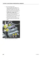
Pressure Relief Valve - Setting Procedures (For RT)
1. Main Relief Valve
a. Instrumentation / Setup:
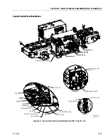
1. Install a pressure gauge, 5000 PSI or higher, at the
port M on the main control valve located in the
hydraulic compartment on the right-hand side of
the machine (see Figure 4-19.).
b. Pressure Setting Check:
1. Turn machine on and start the engine.
2. Enter "Level 1 Access" mode on JLG analyzer.
3. Navigate to the “SERVICE” menu and then
"SER VICE: SET MAIN RELIEF?"
4. Enter the access code 51788 and press enter to
activate main relief pressure setting mode.
NOTE:
This will cause the engine speed to increase to allow
for proper measurement.
5. If the pressure gauge reads more than 50 PSI
above or below 3800 PSI (262 bar), adjustment is
required (follow steps in the “Pressure Setting
Adjustment” portion. If no adjustment is required
press the escape button on the analyzer to exit
main relief pressure setting mode.
Figure 4-19. Pressure Gauge Installation
Summary of Contents for ERT2669
Page 2: ......
Page 4: ...INTRODUCTION A 2 31215923 REVISON LOG Original Issue A January 08 2021...
Page 12: ...viii 31215923 TABLE OF CONTENTS...
Page 40: ...SECTION 1 SPECIFICATIONS 1 22 31215923...
Page 58: ...SECTION 2 GENERAL 2 18 31215923...
Page 187: ...SECTION 4 BASIC HYDRAULIC INFORMATION SCHEMATICS 31215923 4 11...
Page 206: ...SECTION 4 BASIC HYDRAULIC INFORMATION SCHEMATICS 4 30 31215923...
Page 225: ...SECTION 4 BASIC HYDRAULIC INFORMATION SCHEMATICS 31215923 4 49...
Page 242: ...SECTION 4 BASIC HYDRAULIC INFORMATION SCHEMATICS 4 66 31215923...
Page 307: ...SECTION 5 JLG CONTROL SYSTEM 31215923 5 65...
Page 334: ...SECTION 6 LSS SETUP CALIBRATION SERVICE 6 12 31215923...
Page 362: ...SECTION 7 GENERAL ELECTRICAL INFORMATION SCHEMATICS 7 28 31215923...
Page 374: ...SECTION 7 GENERAL ELECTRICAL INFORMATION SCHEMATICS 7 40 31215923...
Page 375: ......


