background image

SECTION 3 - USER RESPONSIBILITIES AND MACHINE CONTROL

3-6

– JLG Lift –

3120883

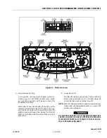
3.

Rotate.

A three position ROTATE control switch permits rota-
tion of the platform when positioned to left or right.

4.

Platform Leveling Override.

A three position LEVEL control switch allows the
operator to compensate for any difference in the
automatic self leveling system by positioning the
control switch to UP or DOWN.

5.

Articulating Jib Boom (If equipped)

The Articulating Jib Boom control switch provides
raising and lowering of the jib when positioned up or
down.

6.

Lower Boom Lift.

Provides for raising and lowering of Lower Boom
when positioned to UP or DOWN.

7.

Upper Boom Lift.

Provides for raising and lowering of Upper Boom
when positioned to UP or DOWN.

8.

Telescope. 

Provides for extension and retraction of Upper Boom
when positioned to IN or OUT.

9.

Swing.

The SWING control switch provides 360 degrees
non-continuous turntable rotation. To activate
SWING, position switch to LEFT or RIGHT.

10.

Circuit Breakers. 

The circuit breakers open (pop out) to indicate a
short or overload somewhere on the machine.

11.

Battery Indicator and Hourmeter.

An hourmeter, installed in the upper portion of the
Ground Control Box, registers the amount of
machine operating time. The hourmeter registers up
to 9,999.9 hours and cannot be reset.

12.

System Distress Indicator.

The system distress indicator lights to signify an
abnormal condition for the generator engine (high
oil temperature or low oil pressure) or, on all electric
machines, an electrical system fault.

NOTE: The engine will automatically shut down under the

following conditions:

High Oil Temperature
Low Oil Pressure
Engine Overspeed
Overvoltage

NOTE: The engine will not start if the batteries are fully

charged or if the Generator Enable switch on the
platform console is not in the on position.

13.

Generator/Engine Start Button.

The generator/engine start push-button switch
allows the generator to be started manually to top-
off the battery charge. The generator will start auto-
matically when the batteries reach a low-charge
state and the Generator Enable switch on the plat-
form console is in the on position.

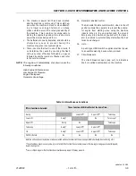
Platform Control Station

1.

Footswitch.

The footswitch is a safety feature. To operate any
function, the footswitch must be depressed and the
function selected within seven seconds. The enable
light in the light panel indicates that the controls are
enabled; as long as functions continue to be used
the controls remain enabled. If a function is not
selected within seven seconds, or if a seven second
lapse between ending one function and beginning
the next function, the enable light will go out and the
footswitch must be recycled to re-enable the con-
trols.

Releasing the footswitch removes power from all
controls and applies the drive brakes.

TO AVOID SERIOUS INJURY, DO NOT REMOVE, MODIFY OR DIS-
ABLE THE FOOTSWITCH BY BLOCKING OR ANY OTHER MEANS.

FOOTSWITCH MUST BE DEPRESSED PRIOR TO ACTIVATING ANY
FUNCTION CONTROL, OTHERWISE THE FUNCTION WILL NOT
OPERATE.

FOOTSWITCH MUST BE ADJUSTED SO THAT FUNCTIONS WILL
OPERATE WHEN PEDAL IS APPROXIMATELY AT ITS CENTER OF
TRAVEL. IF SWITCH OPERATES WITHIN LAST 1/4" OF TRAVEL,
TOP OR BOTTOM, IT SHOULD BE ADJUSTED.

Updated 8-18-99

Summary of Contents for E45A

Page 1: ...lmartin Place Tannochside Park Uddingston Scotland G71 5PH Telephone 01698 811005 Fax 01698 811055 AUSTRALIAN OFFICE JLG INDUSTRIES AUSTRALIA P 0 Box 972 11 Bolwarra Road Port MacQuarie N S W 44 Austr...

Page 2: ......

Page 3: ...APPLICATION AND OPERATION PROPER SAFETY PRACTICES ARE THE RESPONSIBILITY OF THE USER AND HIS OPER ATING PERSONNEL ALL INSTRUCTIONS IN THIS MANUAL ARE BASED ON THE USE OF THE MACHINE UNDER PROPER OPER...

Page 4: ...FOREWORD b JLG Lift 3120883 This page left blank intentionally...

Page 5: ...marked as to their function 4 The controls shall be tested each day prior to use to determine that they are in safe operating condition 5 All personnel in the platform shall at all times wear approve...

Page 6: ...10 2 11 Updated 6 1 99 3 10 thru 3 12 Updated 6 1 99 6 1 Updated 6 1 99 3 7 Updated 7 13 99 3 13 Updated 7 13 99 2 11 Updated 8 4 99 4 1 Updated 8 4 99 4 5 thru 4 7 Updated 8 4 99 3 5 thru 3 8 Updated...

Page 7: ...PONSIBILITIES AND MACHINE CONTROL 3 1 General 3 1 3 2 Personnel Training 3 1 3 3 Operating Characteristics and Limitations 3 2 3 4 Controls and Indicators 3 2 SECTION 4 MACHINE OPERATION 4 1 Descripti...

Page 8: ...rt 2 10 2 4 Torque Chart 2 12 3 1 Position of Least Forward Stability 3 3 3 2 Position of Least Backward Stability 3 4 3 3 Ground Control Station 3 5 3 4 Platform Console 3 7 3 5 Caution Danger Warnin...

Page 9: ...appli cation and or operation JLG Industries Inc should be consulted MODIFICATION OR ALTERATION OF AN AERIAL PLATFORM SHALL BE MADE ONLY WITH PRIOR WRITTEN PERMISSION OF THE MANUFACTURER 1 2 DRIVING...

Page 10: ...IONAL 30 000 VOLTS OR LESS 1 4 PRE OPERATIONAL READ YOUR MANUAL UNDERSTAND WHAT YOU VE READ THEN BEGIN OPERATIONS ALLOW ONLY AUTHORIZED AND QUALIFIED PER SONNEL TO OPERATE MACHINE WHO HAVE DEM ONSTRAT...

Page 11: ...VICED AND MAINTAINED ACCORDING TO THE MANUFACTURERS SPECIFICATIONS AND SCHEDULE ENSURE DAILY INSPECTION AND FUNCTION CHECK IS PERFORMED PRIOR TO PLACING MACHINE INTO OPERATION NEVER DISABLE OR MODIFY...

Page 12: ...DRIVING ALWAYS POSITION BOOM OVER REAR DRIVE AXLE IN LINE WITH DIRECTION OF TRAVEL REMEMBER IF BOOM IS OVER FRONT STEER AXLE DIRECTION OF STEER AND DRIVE MOVEMENT WILL BE OPPO SITE FROM NORMAL OPERAT...

Page 13: ...BEGIN OPERATIONS PRIOR TO ENTERING AND EXITING PLATFORM AT GROUND LEVEL FULLY LOWER THE BOOM EXTEND BOOM UNTIL END OF FLY BOOM CON TACTS GROUND WITH BOOM LIFT IN THIS CONFIG URATION ENTER AND OR EXIT...

Page 14: ...TION LADDERS STEPS OR SIMILAR ITEMS ON UNIT TO PROVIDE ADDITIONAL REACH FOR ANY PURPOSE WHEN RIDING IN OR WORKING FROM PLATFORM BOTH FEET MUST BE FIRMLY POSITIONED ON THE FLOOR KEEP OIL MUD AND SLIPPE...

Page 15: ...H TO THE DESIRED POSITION OPERATE LEVERS WITH SLOW EVEN PRESSURE DO NOT CARRY MATERIALS ON PLATFORM RAILING UNLESS APPROVED BY JLG INDUSTRIES INC NEVER PUSH OR PULL THE MACHINE OR OTHER OBJECTS BY TEL...

Page 16: ...XTENDED OR RETRACTED FOR ANY LENGTH OF TIME ALWAYS BUMP CONTROL IN OPPOSITE DIRECTION SLIGHTLY WHEN FUNCTION BEING USED REACHES END OF TRAVEL THIS APPLIES TO MACHINES IN OPERATION OR IN STOWED MODE DO...

Page 17: ...ing checklist provides a systematic inspection to assist in detecting defective damaged or improperly installed parts The checklist denotes the items to be inspected and conditions to examine Frequent...

Page 18: ...witch connections and plunger for cor rosion and security 5 Check Lower Upright cross pins and hydraulic lines for damage wear lubrication leakage and security 6 Check Lower Upright for damage wear lu...

Page 19: ...r chafing 5 Check Platform Rotator mechanism for proper oper ation damage and security NOTE Check all DANGER WARNING CAUTION and INSTRUCTION placards for legibility and security on the entire machine...

Page 20: ...ally and manually Lower switch cuts out drive speed when Lower Boom is above horizontal Upper switch cuts out drive speed when Upper Boom is above horizontal Only creep drive speed will continue to fu...

Page 21: ...e forward and reverse check for proper opera tion 10 Steer left and right check for proper operation 11 Footswitch FOOTSWITCH MUST BE ADJUSTED SO THAT FUNCTIONS WILL OPERATE WHEN PEDAL IS APPROXIMATEL...

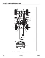
Page 22: ...SECTION 2 PREPARATION AND INSPECTION 2 6 JLG Lift 3120883 Figure 2 2 Daily Walk Around Inspection Sheet 1 of 3...

Page 23: ...loose or missing hardware 8 Limit Switches Switches operable no visible dam age 9 Drive Axle and Motor No loose or missing hard ware No visible damage no evidence of leakage 10 Drive Wheel Tire Assem...

Page 24: ...ly positioned and do not get pinched Close battery compartment cover 6 Start hydraulic system and ensure that it functions properly 24 Tie Rod Ends and Steering Spindles No loose or missing parts no v...

Page 25: ...OR A FLAME NEAR BATTERY DURING SERVIC ING ALWAYS WEAR EYE AND HAND PROTECTION WHEN SER VICING BATTERIES Battery Charging On Board Charger 1 For maximum battery life a Avoid completely discharging the...

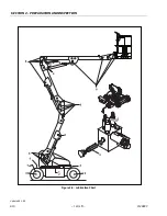
Page 26: ...SECTION 2 PREPARATION AND INSPECTION 2 10 JLG Lift 3120883 Figure 2 3 Lubrication Chart Updated 6 1 99...

Page 27: ...ng Repack A R MPG X 7 Spindles Bushing N A A R LL AtSpindle BushingReplacement CoatI D ofbushingspriortoinstallingking pins 8 Boom Pivot Pins Bushing N A A R LL Atboompivotpins bushingreplacement Coat...

Page 28: ...735 0 8484 0 5740 0 4623 0 3604 0 2700 0 1969 0 1331 0 0925 0 0508 0 0808 0 0445 0 0356 0 0232 0 0153 0 0374 0 0258 0 0168 2 7254 2 1742 1 6840 1 2929 0 9474 0 6502 0 5156 0 4061 0 3015 0 2230 0 1473...

Page 29: ...ency controls and safety systems 2 Knowledge and understanding of this manual and of the control markings instructions and warnings on the machine itself 3 Knowledge and understanding of all safety wo...

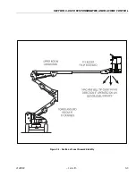
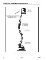
Page 30: ...lled FORWARD stability and BACKWARD stability The machine s position of least FORWARD stability is shown in Figure 3 1 and its position of least BACKWARD stability is shown in Figure 3 2 TO AVOID FORW...

Page 31: ...SECTION 3 USER RESPONSIBILITIES AND MACHINE CONTROL 3120883 JLG Lift 3 3 Figure 3 1 Position of Least Forward Stability...

Page 32: ...SECTION 3 USER RESPONSIBILITIES AND MACHINE CONTROL 3 4 JLG Lift 3120883 Figure 3 2 Position of Least Backward Stability...

Page 33: ...SECTION 3 USER RESPONSIBILITIES AND MACHINE CONTROL 3120883 JLG Lift 3 5 Figure 3 3 Ground Control Station Updated 8 18 99...

Page 34: ...ctrical system fault NOTE The engine will automatically shut down under the following conditions High Oil Temperature Low Oil Pressure Engine Overspeed Overvoltage NOTE The engine will not start if th...

Page 35: ...alarm will beep once During this time the lights on the indicator panel will also blink once as a bulb check 3 Lower Boom Lift Provides for raising and lowering of Lower and Mid Boom when positioned...

Page 36: ...ler Posi traction occurs by chang ing the drive motors from a series to parallel arrangement causing available power to be distrib uted evenly between the two drive wheels The con trol system may also...

Page 37: ...he Generator Enable control switch when in the off position allows the operator to prevent the genera tor engine from starting when using the machine indoors When in the on position and the ground Eme...

Page 38: ...SECTION 3 USER RESPONSIBILITIES AND MACHINE CONTROL 3 10 JLG Lift 3120883 Figure 3 5 Caution Danger Warning Decal Location Updated 6 1 99...

Page 39: ...TO THE JLG OPERATION AND SAFETY MANUAL TO ENSURE SAFE OPERATION OF THIS MACHINE 1 CHECK TYRES AND THEIR CONDITION 2 CHECK BOOM AND AXLE CUT OUT SWITCHES 3 CHECK SAFETY PROTECTION ITEMS 4 CHECK ALL OPE...

Page 40: ...MADE TO THE JLG OPERATION AND SAFETY MANUAL TO ENSURE SAFE OPERATION OF THIS MACHINE 1 CHECK TYRES AND THEIR CONDITION 2 CHECK BOOM AND AXLE CUT OUT SWITCHES 3 CHECK SAFETY PROTECTION ITEMS 4 CHECK A...

Page 41: ...SECTION 3 USER RESPONSIBILITIES AND MACHINE CONTROL 3120883 JLG Lift 3 13 Figure 3 6 Control Panel Symbols Sheet 1 of 2 Updated 7 13 99...

Page 42: ...SECTION 3 USER RESPONSIBILITIES AND MACHINE CONTROL 3 14 JLG Lift 3120883 Figure 3 7 Control Panel Symbols Sheet 2 of 2...

Page 43: ...fety man ager and that the machine be taken out of service until all discrepancies are corrected The JLG Lift is not intended to be used to lift material other than supplies which personnel in the pla...

Page 44: ...ATER DRIVE FUNCTION WILL STOP REMOVE FOOT FROM FOOT SWITCH AND DEPRESS FOOTSWITCH TO RESET DO NOT DRIVE WITH BOOM ABOVE HORIZONTAL EXCEPT ON A SMOOTH FIRM AND LEVEL SURFACE TO AVOID LOSS OF TRAVEL CON...

Page 45: ...control switch is positioned to the RIGHT and held until desired position is reached 4 7 BOOM A RED TILT WARNING LIGHT IS LOCATED ON THE CONTROL CONSOLE WHICH LIGHTS WHEN THE CHASSIS IS ON A 3 DEGREE...

Page 46: ...operate as a conventional battery operated unit The batteries can be used until they are fully discharged Manual Charge Operating Mode The generator will operate in manual mode always when the follow...

Page 47: ...n the stowed position 2 Remove all loose items from the machine 3 Secure the chassis and the platform using straps or chains of adequate strength 4 12 BOOM SYNCHRONIZING PROCEDURE NOTE If the Lower Bo...

Page 48: ...SECTION 4 MACHINE OPERATION 4 6 JLG Lift 3120883 Figure 4 2 Upright Positioning Updated 8 4 99...

Page 49: ...SECTION 4 MACHINE OPERATION 3120883 JLG Lift 4 7 Figure 4 3 Lifting Chart Updated 9 21 99...

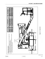
Page 50: ...SECTION 4 MACHINE OPERATION 4 8 JLG Lift 3120883 Figure 4 4 Chassis Platform Tie Down Updated 3 15 00...

Page 51: ...els and wheel bearings from dirt grease mud rocks etc 5 6 BATTERY PACKS Spare battery packs are available to enable the operator to remove battery packs for charging and replace them with fresh batter...

Page 52: ...SECTION 5 OPTIONAL EQUIPMENT 5 2 JLG Lift 3120883 This page left blank intentionally...

Page 53: ...t that sta tion and shut down the machine CHECK DAILY TO MAKE SURE EMERGENCY STOP SWITCH IS FUNCTIONING AND THAT CONTROL INSTRUCTIONS ARE IN PLACE AND LEGIBLE Ground Control Station The Ground Control...

Page 54: ...adequate or malfunc tion when used Platform or Boom Caught Overhead If the platform or boom becomes jammed or snagged in overhead structures or equipment do not continue opera tion of the machine from...

Page 55: ...SECTION 7 INSPECTION AND REPAIR LOG 3120883 JLG Lift 7 1 SECTION 7 INSPECTION AND REPAIR LOG Table 7 1 Inspection and Repair Log Date Comments...

Page 56: ...SECTION 7 INSPECTION AND REPAIR LOG 7 2 JLG Lift 3120883 Table 7 1 Inspection and Repair Log Date Comments...

Page 57: ...ith regard to the current ownership of JLG Products Please return completed form to the JLG Product Safety Reliability Department via facsimile 717 485 6573 or mail to address as specified on the back...

Page 58: ......

Page 59: ......

Page 60: ...Rua Eng Carlos Stevenson 80 Suite 71 13092 310 Campinas SP Brazil Phone 55 19 3295 0407 Fax 55 19 3295 1025 JLG Europe B V Jupiterstraat 234 2132 HJ Foofddorp The Netherlands Phone 31 23 565 5665 Fax...

Reviews: