background image

SECTION 4 - MACHINE OPERATION

3121716

4-17

4.15

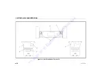
MACHINE LIFTING AND TIE DOWN

See Figure 4-5.

Lifting

1.

Refer to the Serial Number Plate, refer to the Specifications
section of this manual, or weigh the individual unit to find
out the Gross Vehicle Weight.

2.

Place the boom in the stowed position.

3.

Remove all loose items from the machine.

4.

Attach lifting device and equipment only to the designated 
lifting points.

5.

Properly adjust the rigging to prevent damage to the
machine and so the machine remains level.

Tie Down

1.

Place the boom in the stowed position.

2.

Remove all loose items from the machine.

3.

Secure the chassis and the platform using straps or chains of
adequate strength.

To 

order 

go 

to 

Discount-Equipment.com

Summary of Contents for E400A Narrow

Page 1: ...ual with the machine at all times AS NZS Boom Lift Models E400A Narrow E400AJP E400AJP Narrow M400AJP M400AJP Narrow S N 0300208530 to Present Seeinsidefrontcoverforexceptions 3121716 November 5 2018...

Page 2: ...Curtis Gehl Pavers Heli Honda ICS PowerGrit IHI Partner Imer Clipper MMD Koshin Rice CH E General Equip ment Amida Coleman NAC Gradall Square Shooter Kent Stanley Tamco Toku Hatz Kohler Robin Wiscons...

Page 3: ...lead which are known to the State of California to cause cancer and birth defects or other reproductive harm To minimize exposure avoid breathing exhaust do not idle the engine except as necessary ser...

Page 4: ...lessees with the precautions and operating procedures essential for the safe and proper machine operation for its intended purpose Due to continuous product improvements JLG Industries Inc reserves t...

Page 5: ...POTENTIALLY HAZARDOUS SITUATION IF NOT AVOIDED MAY RESULT IN MINOR OR MODERATE INJURY IT MAY ALSO ALERT AGAINST UNSAFE PRACTICES THIS DECAL WILL HAVE A YELLOW BACKGROUND IMPORTANT INDICATES INFORMATI...

Page 6: ...D IN AN ACCIDENT INVOLVING BODILY INJURY OR DEATH OF PERSONNEL OR WHEN SUBSTANTIAL DAMAGE HAS OCCURRED TO PER SONAL PROPERTY OR THE JLG PRODUCT Contact Product Safety and Reliability Department JLG In...

Page 7: ...d 3121716 REVISION LOG Original Issue A July 6 2015 Revised B May 30 2018 Revised C June 29 2018 Revised Covers Prop 65 Revised D November 5 2018 T o o r d e r g o t o D i s c o u n t E q u i p m e n...

Page 8: ...n 2 1 Operator Responsibility 2 1 2 2 PREPARATION INSPECTION AND MAINTENANCE 2 2 Pre Start Inspection 2 5 Daily Walk Around Inspection 2 6 Function Check 2 9 SkyGuard Function Test 2 11 SECTION 3 MACH...

Page 9: ...kyEye 4 15 SkyGuard Function Table 4 15 4 13 BOOM SYNCHRONIZING PROCEDURE 4 16 4 14 SHUT DOWN AND PARK 4 16 4 15 MACHINE LIFTING AND TIE DOWN 4 17 Lifting 4 17 Tie Down 4 17 SECTION 5 EMERGENCY PROCED...

Page 10: ...CATION 7 11 7 4 BATTERY MAINTENANCE AND CHARGING 7 17 Battery Maintenance Quarterly 7 17 Optional On Board Generator 7 18 Battery Charging On Board Charger 7 18 7 5 TIRES WHEELS 7 19 Tire Inflation 7...

Page 11: ...d Side Slopes 4 7 4 4 Traveling on a Grade 4 8 4 5 Lifting Chart 4 18 4 6 Decal Installation Sheet 1 of 6 4 19 4 7 Decal Installation Sheet 2 of 6 4 20 4 8 Decal Installation Sheet 3 of 6 4 21 4 9 Dec...

Page 12: ...1 Available Accessories 6 1 7 1 Operating Specifications 7 1 7 2 Capacities 7 3 7 3 Tire Specifications 7 3 7 4 Dimensional Data 7 4 7 5 Torque Requirements 7 5 7 6 Hydraulic Oil 7 5 7 7 Mobil DTE 10...

Page 13: ...Curtis Gehl Pavers Heli Honda ICS PowerGrit IHI Partner Imer Clipper MMD Koshin Rice CH E General Equip ment Amida Coleman NAC Gradall Square Shooter Kent Stanley Tamco Toku Hatz Kohler Robin Wiscons...

Page 14: ...of the machine has been completed under the supervision of an experienced and quali fied operator This section contains the responsibilities of the owner user oper ator lessor and lessee concerning s...

Page 15: ...in to your utilization and application of the machine Workplace Inspection Precautions to avoid all hazards in the work area must be taken by the user before and during operation of the machine Do not...

Page 16: ...slippery substances from footwear and plat form floor 1 3 OPERATION General Machine operation requires your full attention Bring the machine to a full stop before using any device i e cell phones two...

Page 17: ...e of drugs or alcohol or who are subject to seizures dizziness or loss of physical control must not operate this machine Hydraulic cylinders are subject to thermal expansion and con traction This may...

Page 18: ...all times Never position ladders boxes steps planks or similar items on unit to provide additional reach for any purpose Keep oil mud and slippery substances cleaned from footwear and the platform flo...

Page 19: ...r equip ment from any electrical line or apparatus carrying up to 50 000 volts One foot additional clearance is required for every additional 30 000 volts or less Table 1 1 Minimum Approach Distances...

Page 20: ...ork practices near energized equipment DO NOT MANEUVER MACHINE OR PERSONNEL INSIDE PROHIBITED ZONE MAD ASSUME ALL ELECTRICAL PARTS AND WIRING ARE ENERGIZED UNLESS KNOWN OTH ERWISE Tipping Hazards The...

Page 21: ...chine Use cranes forklift trucks or other appropriate equipment to stabilize machine Do not operate the machine when wind conditions including gusts may exceed 28 mph 12 5 m s Factors affecting wind s...

Page 22: ...3 8 12 3 4 5 4 Gentlebreeze Leavesandsmallertwigsinconstantmotion 4 13 18 5 5 7 9 Moderatebreeze Dustandloosepaperraised Smallbranchesbegintomove 5 19 24 8 0 10 7 Freshbreeze Smallertreessway 6 25 31...

Page 23: ...ording to conditions of ground surface congestion visibility slope location of personnel and other factors which may cause collision or injury to personnel Be aware of stopping distances in all drive...

Page 24: ...nserted at the appropriate points in this manual and in the Ser vice and Maintenance Manual It is of utmost importance that maintenance personnel pay strict attention to these precautions to avoid pos...

Page 25: ...ound for welding When performing welding or metal cutting operations pre cautions must be taken to protect the chassis from direct exposure to weld and metal cutting spatter Do not refuel the machine...

Page 26: ...ays wear hand eye and face protection when servicing batteries Ensure that battery acid does not come in contact with skin or clothing BATTERY FLUID IS HIGHLY CORROSIVE AVOID CONTACT WITH SKIN AND CLO...

Page 27: ...Curtis Gehl Pavers Heli Honda ICS PowerGrit IHI Partner Imer Clipper MMD Koshin Rice CH E General Equip ment Amida Coleman NAC Gradall Square Shooter Kent Stanley Tamco Toku Hatz Kohler Robin Wiscons...

Page 28: ...SECTION 1 SAFETY PRECAUTIONS 1 14 3121716 NOTES T o o r d e r g o t o D i s c o u n t E q u i p m e n t c o m...

Page 29: ...s 4 Use of approved fall protection device 5 Enough knowledge of the mechanical operation of the machine to recognize a malfunction or potential malfunc tion 6 The safest means to operate the machine...

Page 30: ...ial work platforms The fre quency of inspections and maintenance must be increased as necessary when the machine is used in a harsh or hostile environ ment if the machine is used with increased freque...

Page 31: ...3monthsor150hours whichevercomesfirst or Outofserviceforaperiodofmorethan3months or Purchasedused Owner Dealer orUser QualifiedJLGMechanic ServiceandMaintenanceManual andapplicableJLGinspectionform An...

Page 32: ...der inside 5 MasterCylinder 6 UpperUpright 7 UpperLiftCylinder 8 MidLiftCylinder 9 LowerBoom 10 Turntable 11 Frame 12 SteerWheels 13 DriveWheels 14 BatteryBox 15 LowerLiftCylinder 16 LowerLink 17 Lowe...

Page 33: ...pection Perform as instructed 6 Battery Charge as required 7 Fuel Generator Equipped Machines Add the proper fuel as necessary 8 Engine Oil Supply Generator Equipped Machines Ensure the engine oil lev...

Page 34: ...SECTION 2 USER RESPONSIBILITIES MACHINE PREPARATION AND INSPECTION 2 6 3121716 Daily Walk Around Inspection 0 0 T o o r d e r g o t o D i s c o u n t E q u i p m e n t c o m...

Page 35: ...astened and that no visible damage exists in addition to any other criteria mentioned 1 Platform and Gate Assembly Platform mounting pins secure Footswitch in good working order not modified dis abled...

Page 36: ...ent Right Side Batteries have proper electrolyte level cables tight no visible damage or corro sion 15 Cowling and Latches See Note 16 Battery Charger See Note 17 Brake Steer Valve See Note 18 Boom Up...

Page 37: ...k for smooth operation 3 If tower boom does not rest on stop with machine in the stowed position this indicates upright is out of plumb 4 Telescope boom In and Out several cycles at various degrees of...

Page 38: ...ERATE WHEN PEDAL IS APPROXIMATELY AT ITS CENTER OF TRAVEL IF SWITCH OPERATES WITHIN LAST 1 4 6 MM OF TRAVEL TOP OR BOTTOM IT SHOULD BE ADJUSTED FOOTSWITCH MUST BE DEPRESSED PRIOR TO ACTIVATING ANY FUN...

Page 39: ...n path of sensor beam 3 Once the sensor has been activated verify the following conditions a Telescope out function stops and telescope in function operates for a short duration b The horn sounds c If...

Page 40: ...Curtis Gehl Pavers Heli Honda ICS PowerGrit IHI Partner Imer Clipper MMD Koshin Rice CH E General Equip ment Amida Coleman NAC Gradall Square Shooter Kent Stanley Tamco Toku Hatz Kohler Robin Wiscons...

Page 41: ...SECTION 2 USER RESPONSIBILITIES MACHINE PREPARATION AND INSPECTION 2 12 3121716 NOTES T o o r d e r g o t o D i s c o u n t E q u i p m e n t c o m...

Page 42: ...ymbols and the correspond ing functions NOTE The indicator panels use different shaped symbols to alert the operator to different types of operational situations that could arise The meaning of those...

Page 43: ...genera tor engine high oil temperature or low oil pressure or on electric machines an elec trical system fault NOTE The engine will automatically shut down under the following conditions High Oil Tem...

Page 44: ...Generator EngineStartButton 4 IndicatorGauge 5 ChargerStatus 6 Telescope 7 MachineSafetySystemOverride MSSO IfEquipped 8 Swing 9 FunctionEnable 10 CircuitBreakers 11 Power EmergencyStop 12 Platform Gr...

Page 45: ...of the battery charger The red LED indicates Charging Abnormal The yellow LED indicates charging in progress The green LED indicates charging is complete 6 Telescope Provides for extension and retract...

Page 46: ...r to the platform control console when positioned to Platform With the switch key in the Ground posi tion power is shut off to platform and only ground controls are operable NOTE With Platform Ground...

Page 47: ...ding descending a grade 18 Rotate A three position Rotate control switch permits rotation of the platform when positioned to left or right Platform Control Console See Figure 3 2 1 Speed Mode Activati...

Page 48: ...rgencyStop 5 GeneratorEnable 6 DriveOrientationOverride 7 Drive Steer 8 Telescope 9 Lights 10 Jib 11 JibSwing 12 SoftTouch SkyGuardOverride IfEquipped 13 LowerBoomLift 14 PlatformRotate 15 FunctionSpe...

Page 49: ...d The Generator Enable control switch when in the off position allows the operator to prevent the generator engine from starting when using the machine indoors When in the on position and the ground E...

Page 50: ...horizontal or the upper boom is raised approximately 16 inches 40 64 cm above boom rest the high drive function will automatically switch to low drive This also occurs when Function Speed Control is c...

Page 51: ...tdown situation If equipped with SkyGuard the switch enables functions cut out by the Sky guard system to be operated again allowing the operator to resume use of machine functions If equipped with bo...

Page 52: ...oystick pull up on the locking ring below the handle NOTE The Main Boom Lift Swing joystick is spring loaded and will automatically return to neutral off position when released 16 Main Lift Swing Cont...

Page 53: ...g No Telescope Telescope DriveandSteer Swing LowerLift UpperLift Jib DriveandSteer Swing LowerLift UpperLift Telescope PlatformRotate DriveandSteer No No No No Note Boomfunctionsmaybeslowerwhenselecte...

Page 54: ...zontal then reposi tion machine so that it is level before continuing operation If the boom is above horizontal and the machine is on a slope the tilt alarm warning light will illuminate and an alarm...

Page 55: ...1 Tilt 2 PlatformOverload 3 SystemDistress 4 DriveOrientation 5 FootswitchEnable 6 BatteryCharge 7 LowBattery 8 SkyGuard 9 SoftTouch 10 CreepSpeed Figure 3 3 Platform Control Indicator Panel T o o r...

Page 56: ...xceed the rated gradeability of the machine This condition is comparable to stalling the engine by asking it to pro vide more power than it was designed to do c The batteries are nearly depleted and s...

Page 57: ...the footswitch must be released and depressed again to enable the controls Releasing the footswitch removes power from all controls and applies the drive brakes TO AVOID SERIOUS INJURY DO NOT REMOVE M...

Page 58: ...9 Soft Touch Indicator If Equipped When illuminated Yellow the Soft Touch bumper is against an object All controls are disabled until the override button is pushed at which time controls are active in...

Page 59: ...Curtis Gehl Pavers Heli Honda ICS PowerGrit IHI Partner Imer Clipper MMD Koshin Rice CH E General Equip ment Amida Coleman NAC Gradall Square Shooter Kent Stanley Tamco Toku Hatz Kohler Robin Wiscons...

Page 60: ...SECTION 3 MACHINE CONTROLS AND INDICATORS 3 18 3121716 NOTES T o o r d e r g o t o D i s c o u n t E q u i p m e n t c o m...

Page 61: ...right of the stowed position The machine has a Ground Con trol Station which will override the Platform Control Station Ground Controls operate Upper and Lower Boom Lift and Swing and are to be used i...

Page 62: ...ncy Stop The Power Emergency Stop switch when pulled out on provides battery power for all machine functions The switch should be pushed in off when recharging the batteries or parking the machine ove...

Page 63: ...4 1 Position of Least Forward Stability MACHINEWILL TIPOVER INTHIS DIRECTIONIFOPERATEDONAN OUT OF LEVELSURFACE FLYBOOM FULLYEXTENDED UPPERBOOM HORIZONTAL TOWERANDMID BOOMAT 33DEGREES T o o r d e r g...

Page 64: ...ward Stability LOWER BOOM FULLY ELEVATED MID BOOM FULLY ELEVATED UPPER BOOM FULLY ELEVATED AND RETRACTED PLATFORM ROTATED 90 DEGREES MACHINE WILL TIP OVER IN THIS DIRECTION IF OPERATED ON AN OUT OF LE...

Page 65: ...E AND CORRECT CAUSE BEFORE RESUMING ANY OPERATION 4 4 TRAVELING DRIVING NOTE For units equipped with optional tilt cutout verify that the drive function is cut out when the boom is elevated and tilt a...

Page 66: ...DEPRESSED PRIOR TO ACTIVATING ANY FUNCTION OTHER WISE FUNCTION WILL NOT OPERATE 1 At Platform Controls pull out Emergency Stop switch and activate footswitch 2 Position Drive controller to Forward or...

Page 67: ...SECTION 4 MACHINE OPERATION 3121716 4 7 Figure 4 3 Grade and Side Slopes T o o r d e r g o t o D i s c o u n t E q u i p m e n t c o m...

Page 68: ...econd interval until the drive function is selected Traveling on a Grade When traveling a grade maximum braking and traction are obtained with the boom stowed in position over the rear drive axle and...

Page 69: ...arkets and 230 kg for CE and Australia markets or less proceed with adding weight Platform Level Adjustment 1 Depress footswitch To raise platform position Platform Level control switch Up and hold un...

Page 70: ...M INDICATES CHASSIS IS ON A SEVERE SLOPE 5 DEGREE OR GREATER CHASSIS MUST BE LEVEL BEFORE SWINGING OR RAISING BOOM ABOVE HORIZONTAL TO AVOID TIP OVER IF RED TILT WARNING LIGHT LIGHTS WHEN BOOM IS RAIS...

Page 71: ...on Upper Boom Lift switch to UP or DOWN until desired height is reached 4 8 GENERATOR The machine is equipped with an engine powered DC generator connected in parallel to the 48V DC battery bank Autom...

Page 72: ...generator will operate in manual mode always when the fol lowing three conditions apply 1 Ground Control Emergency Stop Switch is pulled out on and 2 The switch on the platform control console is in...

Page 73: ...atically turn back on when cooled The overload light indicates an output wiring short circuit or a load that is too large for the rating of the inverter 4 10 MACHINE FUNCTION SPEEDS The Function Speed...

Page 74: ...tch are disengaged If the SkyGuard sensor remains activated after function reversal or cutout depress and hold the SkyGuard Override Switch to allow normal functions until the sensor is disengaged Con...

Page 75: ...se Steer Swing Tower Lift Up Tower Lift Down Boom Lift Up Boom Lift Down Boom Tele Out Boom Tele In Jib Lift Jib Swing Basket Level Basket Rotate R C R C R R C R C R C C C C C R IndicatesReversalisAct...

Page 76: ...rged in accordance with instructions in Section 2 to ensure readiness for following workday NOTE Electric machines are equipped with a static strap due to static electricity build ups Strap is located...

Page 77: ...the stowed position 3 Remove all loose items from the machine 4 Attach lifting device and equipment only to the designated lifting points 5 Properly adjust the rigging to prevent damage to the machin...

Page 78: ...SECTION 4 MACHINE OPERATION 4 18 3121716 Figure 4 5 Lifting Chart T o o r d e r g o t o D i s c o u n t E q u i p m e n t c o m...

Page 79: ...SECTION 4 MACHINE OPERATION 3121716 4 19 Figure 4 6 Decal Installation Sheet 1 of 6 T o o r d e r g o t o D i s c o u n t E q u i p m e n t c o m...

Page 80: ...SECTION 4 MACHINE OPERATION 4 20 3121716 Figure 4 7 Decal Installation Sheet 2 of 6 T o o r d e r g o t o D i s c o u n t E q u i p m e n t c o m...

Page 81: ...SECTION 4 MACHINE OPERATION 3121716 4 21 Figure 4 8 Decal Installation Sheet 3 of 6 T o o r d e r g o t o D i s c o u n t E q u i p m e n t c o m...

Page 82: ...SECTION 4 MACHINE OPERATION 4 22 3121716 Figure 4 9 Decal Installation Sheet 4 of 6 T o o r d e r g o t o D i s c o u n t E q u i p m e n t c o m...

Page 83: ...SECTION 4 MACHINE OPERATION 3121716 4 23 Figure 4 10 Decal Installation Sheet 5 of 6 T o o r d e r g o t o D i s c o u n t E q u i p m e n t c o m...

Page 84: ...SECTION 4 MACHINE OPERATION 4 24 3121716 Figure 4 11 Decal Installation Sheet 6 of 6 T o o r d e r g o t o D i s c o u n t E q u i p m e n t c o m...

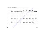
Page 85: ...4 1703798 1705822 1703932 1703933 1703929 1703930 1703931 1703934 1705822 5 1705514 6 1001131269 1700584 7 1706948 1706948 1706948 1706948 1706948 1706948 1706948 1001187083 8 9 1701504 1701504 17015...

Page 86: ...704000 1704002 25 1001193949 1001193949 1001193949 1001193949 1001193949 1001193949 1001193949 1001193949 1001193949 26 1001196811 1001196811 1001196811 1001196811 1001196811 27 1704446 1706378 170441...

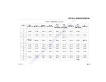
Page 87: ...1704343 1704339 1704340 1704344 1704341 1705670 40 3252347 41 1703804 1701518 1703950 1703951 1703947 1703948 1703949 1703952 1701518 42 Table 4 1 E400A E400AJP Decal Legend Item ANSI 1001178364 D Au...

Page 88: ...1702631 1702631 1702631 1702631 1702631 53 1001121814 1705978 1001121821 1001121921 1001121818 1001121816 1001121823 1001121923 1705978 54 55 56 Table 4 1 E400A E400AJP Decal Legend Item ANSI 10011783...

Page 89: ...1121803 1001121810 1001121920 1705978 66 67 68 69 70 Table 4 1 E400A E400AJP Decal Legend Item ANSI 1001178364 D Aus 1001178378 E Japanese 1001178372 D Korean 1001178374 D Eng Lat Spanish 1001178368 D...

Page 90: ...1705910 1705429 1705430 1001113680 82 1001189882 1001189882 1001189882 1001189882 1001189882 1001189882 1001189882 1001189882 1001189882 Table 4 1 E400A E400AJP Decal Legend Item ANSI 1001178364 D Au...

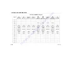
Page 91: ...514 6 1001131269 7 1706948 1001126871 1706948 1706948 1706948 1706948 1706948 1706948 1001187083 8 9 1701504 1701504 1701504 1701504 1701504 1701504 1701504 1701504 1701504 10 1701642 1701642 1701642...

Page 92: ...9 1001193949 1001193949 1001173577 1001193949 26 1001196811 1001196811 1001196811 1001196811 27 1704446 1706378 1704417 1704418 1704454 1704452 1704419 1704453 1706378 28 1704431 1704431 1704431 17044...

Page 93: ...71 1703987 1702265 1702265 1703988 1703991 1705977 48 49 50 1702300 1703814 1702300 1702300 1702300 1702300 1702300 1702300 1703814 51 52 1702631 1702631 1702631 1702631 1702631 1702631 1702631 170263...

Page 94: ...2 1701502 67 1701503 1701503 1701503 68 69 70 1704286 1704286 1001093687 1001093687 1704371 1001093687 1001093687 1001093687 1001093687 71 Table 4 2 M400AJP Decal Legend Item ANSI 1001178362 D Aus 100...

Page 95: ...04885 1704885 1704885 1704885 80 81 1705351 1705351 1705426 1705427 1705910 1705429 1705430 1001113680 82 1001189882 1001189882 1001189882 1001189882 1001189882 1001189882 1001189882 1001189882 100118...

Page 96: ...Curtis Gehl Pavers Heli Honda ICS PowerGrit IHI Partner Imer Clipper MMD Koshin Rice CH E General Equip ment Amida Coleman NAC Gradall Square Shooter Kent Stanley Tamco Toku Hatz Kohler Robin Wiscons...

Page 97: ...SECTION 4 MACHINE OPERATION 4 36 3121716 NOTES T o o r d e r g o t o D i s c o u n t E q u i p m e n t c o m...

Page 98: ...anty consideration on that particular machine FOLLOWING ANY ACCIDENT THOROUGHLY INSPECT THE MACHINE AND TEST ALL FUNCTIONS FIRST FROM THE GROUND CONTROLS THEN FROM THE PLATFORM CON TROLS DO NOT LIFT A...

Page 99: ...damaged or does not operate properly turn off the machine immedi ately Report the problem to the proper maintenance per sonnel Do not operate the machine until it is declared safe for operation 5 4 E...

Page 100: ...as follows 1 Using a 7 8 inch socket and ratchet wrench locate nut on swing worm gear on left side of machine 2 Install wrench on nut and ratchet in the direction desired 5 7 MACHINE SAFETY SYSTEM OVE...

Page 101: ...Curtis Gehl Pavers Heli Honda ICS PowerGrit IHI Partner Imer Clipper MMD Koshin Rice CH E General Equip ment Amida Coleman NAC Gradall Square Shooter Kent Stanley Tamco Toku Hatz Kohler Robin Wiscons...

Page 102: ...SECTION 5 EMERGENCY PROCEDURES 5 4 3121716 NOTES T o o r d e r g o t o D i s c o u n t E q u i p m e n t c o m...

Page 103: ...ACCESSORIES 3121716 6 1 SECTION 6 ACCESSORIES Table 6 1 Available Accessories Accessory Market ANSI USA Only ANSI CSA CE AUS Japan China PipeRacks T o o r d e r g o t o D i s c o u n t E q u i p m e...

Page 104: ...5 KG WHEN INSTALLED WEIGHT IN RACKS PLUS WEIGHT IN PLATFORM MUST NOT EXCEED RATED CAPACITY THE MAXIMUM LOAD IN THE RACKS IS 180 LBS 80 KG EVENLY DISTRIBUTED BETWEEN THE TWO RACKS THE MAXIMUM LENGTH OF...

Page 105: ...en secure with locking pins 2 Loosen and remove tie down straps Place material on racks with weight evenly distributed between both racks 3 Route the tie down straps at each end across loaded mate ria...

Page 106: ...Curtis Gehl Pavers Heli Honda ICS PowerGrit IHI Partner Imer Clipper MMD Koshin Rice CH E General Equip ment Amida Coleman NAC Gradall Square Shooter Kent Stanley Tamco Toku Hatz Kohler Robin Wiscons...

Page 107: ...SECTION 6 ACCESSORIES 6 4 3121716 NOTES T o o r d e r g o t o D i s c o u n t E q u i p m e n t c o m...

Page 108: ...rvice and Maintenance Manual Other Publications Available Service and Maintenance Manual 3121717 Illustrated Parts Manual 3121718 7 2 OPERATING SPECIFICATIONS Table 7 1 Operating Specifications Maximu...

Page 109: ...riveSpeed AboveHorz E M400AJP E400An E M400AJPn 42 44sec 200ft 50 53sec 50ft 45 50sec 200ft 55 68sec 50ft GrossMachineWeight E400An E400AJP M400AJP E400AJPn M400AJPn 13100lb 5942kg 13700lb 6214kg 1393...

Page 110: ...ludingTank 9Gallons 34 1L TorqueHub Drive 17ounces 0 50L Torquehubsshouldbeonehalffulloflubricant Table 7 3 Tire Specifications Size Type Pressure Ply Rating Load Range IN240 55 17 5 Pneumatic 90psi 6...

Page 111: ...mumUpand Over E400An E M400AJP E M400AJPn 21ft 2in 6 41m 22ft 5in 6 83m MachineWidth E M400AJP E400An E M400AJPn 5ft 9in 1 75m 4ft 11in 1 50m WheelBase 6ft 7 0in 2 00m WorkingHeight 46ft 0in 14 02m Pl...

Page 112: ...mparable viscosities If use of hydraulic oil other than Mobil DTE 10 is desired contact JLG Industries for proper recommendations Table 7 5 Torque Requirements Description Torque Value Interval Hours...

Page 113: ...at100 C 4 07cSt at100 F 15 8cSt at212 F 4 07cSt ViscosityIndex 168 Density Kg l 15 C 0 8375 Density lb in3 60 F 0 0302 Table 7 8 Mobil EAL Envirosyn H 32 Specs Type SyntheticBiodegradable ISOViscosit...

Page 114: ...STABILITY Table 7 9 Mobil EAL Envirosyn SHC 32 Specs Type SyntheticBiodegradable ISOViscosityGrade 32 Densityat15 C 936 PourPoint Max 27 F 33 C FlashPoint Min 540 F 282 C Viscosity at40 C 33 1cSt at10...

Page 115: ...If the serial number plate is damaged or missing the machine serial number is stamped on the top left side of the frame and the top left side of the turntable In addition the serial number is stamped...

Page 116: ...SECTION 7 GENERAL SPECIFICATIONS OPERATOR MAINTENANCE 3121716 7 9 Figure 7 2 E450 Maintenance Lubrication Diagram T o o r d e r g o t o D i s c o u n t E q u i p m e n t c o m...

Page 117: ...SECTION 7 GENERAL SPECIFICATIONS OPERATOR MAINTENANCE 7 10 3121716 Figure 7 3 M450 Maintenance Lubrication Diagram T o o r d e r g o t o D i s c o u n t E q u i p m e n t c o m...

Page 118: ...ccess Optional Table 7 11 Lubrication Specifications KEY SPECIFICATIONS MPG MultipurposeGreasehavingaminimumdrippingpointof350degreesF Excellentwaterresistanceandadhesivequalities andbeingofextreme pr...

Page 119: ...all grease fittings into worm gear housing and grease bearings NOTE OG will allow better cycle times than Mobiltac375NC however Mobiltac375NC must be used in dusty environments If the swing function b...

Page 120: ...M400AJPn 5 Gal 19 L Lube HO Interval Check Level daily Change every 2 years or 1200 hours of operation Comments On new machines those recently overhauled or after changing hydraulic oil operate all s...

Page 121: ...rst 50 hrs and every 6 months or 300 hrs thereafter Comments Under certain conditions it may be necessary to replace the hydraulic filter on a more frequent basis A com mon symptom of a dirty filter i...

Page 122: ...nge every 2 years or 1200 hours of operation 6 Wheel Bearings Lube Point s Repack Capacity A R Lube MPG Interval Every 2 years or 1200 hours of operation 7 Spindles Bushing Capacity A R Lube Lithium L...

Page 123: ...ours of operation Comments At boom pivot pins bushing replacement Coat I D of bushings prior to installing pivot pins 9 Engine Lube Point s Fill Cap Capacity Refer to Engine Manual Lube EO Interval 3...

Page 124: ...t electrolyte level of each cell Electrolyte level should be to the ring approximately one inch from top of battery Fill batteries with distilled water only Replace and secure all vent caps 3 Remove b...

Page 125: ...OID INJURY FROM AN EXPLOSION DO NOT SMOKE OR ALLOW SPARKS OR A FLAME NEAR BATTERY DURING SERVICING ALWAYS WEAR EYE AND HAND PROTEC TION WHEN SERVICING BATTERIES Battery Charging On Board Charger 1 For...

Page 126: ...diameter any damage to the bead area cords of the tire If a tire is damaged but is within the above noted criteria the tire must be inspected on a daily basis to insure the damage has not propagated...

Page 127: ...O PREVENT LOOSE WHEELS BROKEN STUDS AND POSSIBLE DANGEROUS SEPARATION OF WHEEL FROM THE AXLE BE SURE TO USE ONLY THE NUTS MATCHED TO THE CONE ANGLE OF THE WHEEL Tighten the lug nuts to the proper torq...

Page 128: ...mmended sequence tighten nuts per wheel torque chart 4 Wheel nuts should be torqued after first 50 hours of operation and after each wheel removal Check torque every 3 months or 150 hours of operation...

Page 129: ...less than 70dB A For combustion engine powered machines guaranteed Sound Power Level LWA per European Directive 2000 14 EC Noise Emission in the Environment by Equipment for Use Outdoors based on tes...

Page 130: ...PAIR LOG 3121716 8 1 SECTION 8 INSPECTION AND REPAIR LOG MachineSerialNumber_______________________________________ Table 8 1 Inspection and Repair Log Date Comments T o o r d e r g o t o D i s c o u...

Page 131: ...Curtis Gehl Pavers Heli Honda ICS PowerGrit IHI Partner Imer Clipper MMD Koshin Rice CH E General Equip ment Amida Coleman NAC Gradall Square Shooter Kent Stanley Tamco Toku Hatz Kohler Robin Wiscons...

Page 132: ...T o o r d e r g o t o D i s c o u n t E q u i p m e n t c o m...

Reviews: